Writing method for optical disc, processing method for information, optical disc apparatus, and information processing apparatus

a writing method and optical disc technology, applied in the field of information processing, can solve problems such as system itself becoming larger, easy to fall out of the track, and easy to write to the optical disc, and achieve the effects of reducing the size of the system, and reducing the number of optical discs

Inactive Publication Date: 2006-03-30
RICOH KK
View PDF4 Cites 11 Cited by
  • Summary
  • Abstract
  • Description
  • Claims
  • Application Information

AI Technical Summary

Benefits of technology

[0027] According to the foregoing description, an object of the invention is to provide an optical disc writing method and an optical writing apparatus, wherein the ZCLV zones can be set to match the mechanical characteristic and the writing characteristic for each disc type, and high-speed writing can be performed without causing track deviation.
[0029] It is an object of the invention to provide an optical disc writing method and an optical writing apparatus, wherein both stable writing and high-speed writing can be achieved. In addition, the writing can be performed at the highest speed without failure in the writing and without losing the writing quality.

Problems solved by technology

Due to influences of the bad mechanical accuracy, burred surface of the optical disc and the eccentricity etc, a track deviation, which means that the light spot for performing the data writing to the optical disc falls out of the track, occurs easily.
This is a severe problem.
Accordingly, it is obvious that the system itself becomes larger and the cost goes up.
When an optical disc with bad characteristic is used in the disc apparatus and the rotates with a high speed, the follow controls of the focusing servo and the tracking servo will fail and the data writing cannot be performed with a high writing speed.
If the mechanical characteristic of the optical disc is worse, there is danger due to the track deviation when the optical disc rotates with a high speed.
Even if the optical discs are the same type, the writing sensitivity and the mechanical characteristic are dispersed due to the unevenness of the manufacturing conditions.
Regarding the optical disc apparatus, because of the unevenness of the assemble accuracy, the chucking accuracy (a shifting amount between the center of the optical disc and the rotational center of the driving motor) when the optical disc is loaded is also uneven, and the relative mechanical accuracy of the optical disc becomes uneven too.
In addition, due to the unevenness of the wavelength of the semiconductor laser, the writing sensitive characteristic is also uneven.
Due to the unevenness of the manufacturing conditions, the maximum possible writing speed is also uneven.
At this time, when the writing speed is lower than the writing speed set by the user, the writing operation does not complete even though the preset writing time has passed, the ill condition for the optical disc apparatus occurs and the personal computer may hang up.
In addition, the user cannot set the writing speed to try to use the optical disc apparatus.
For example, if the user has many of the same optical discs, the limit of the writing speed cannot be found by experiment.

Method used


Image

  • Writing method for optical disc, processing method for information, optical disc apparatus, and information processing apparatus
  • Writing method for optical disc, processing method for information, optical disc apparatus, and information processing apparatus
  • Writing method for optical disc, processing method for information, optical disc apparatus, and information processing apparatus

Examples


first embodiment

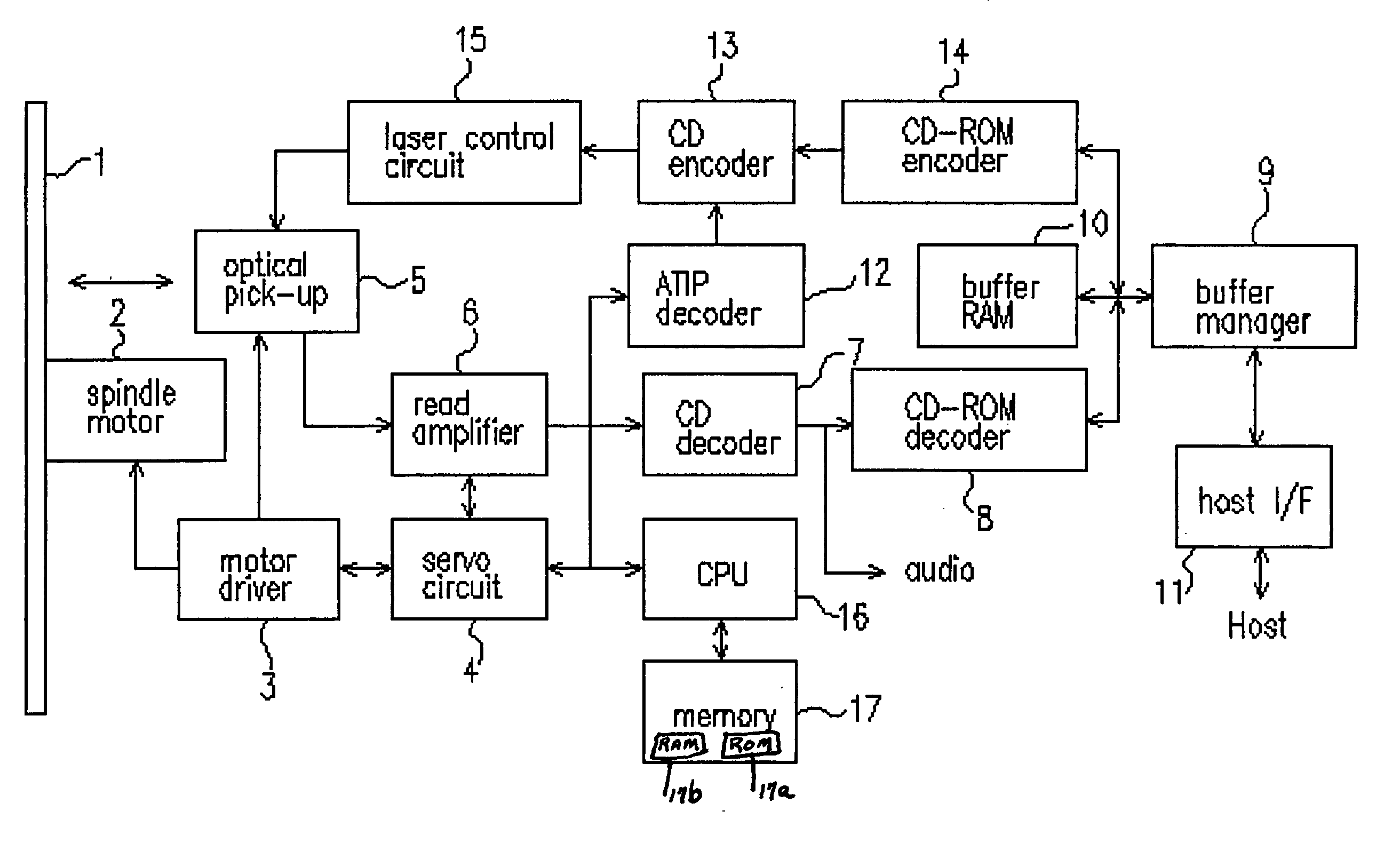
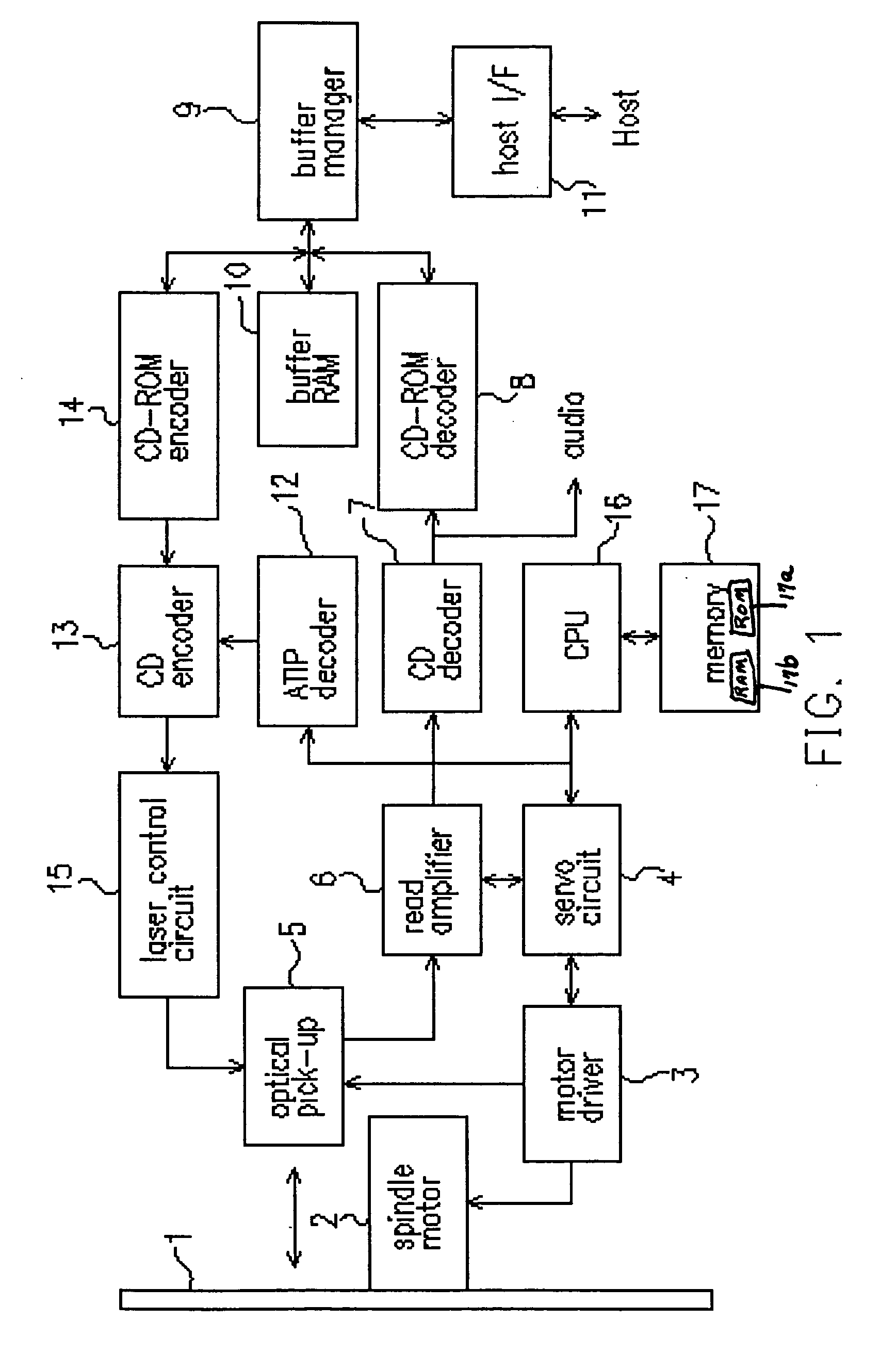
[0118]FIG. 1 shows a schematic block diagram according to the first embodiment of the invention. The optical disc apparatus in the first embodiment is used for writing and / or reproducing information on an optical disc, such as the CD-RW. The optical disc 1 is driven to rotate by a spindle motor 2. The spindle motor 2 is driven and controlled by a motor driver 3 such that the optical disc 1 is rotated under the CLV or the ZCLV control.

[0119] A laser diode 5 emits a laser beam from a laser source, such as a laser diode. The laser beam is focused on a recording surface of the optical disc 1 (the recording medium). An actuator is controlled by a servo circuit 4 to perform a focusing servo control and a tracking servo control, thereby generating a reproducing signal to reproduce data recorded on the optical disc 1, or writing data on the optical disc 1.

[0120] When reproducing data, the reproducing signal obtained by the optical pick-up 5 is amplified by a read amplifier 6 and then digi...

second embodiment

[0135] Next, the second embodiment of the invention is described in detail as follows. The second embodiment performs a ZCLV writing, which is more elaborate than the first embodiment. The CPU 16 controls each element in FIG. 1 to execute the following process. As the optical disc 1 is inserted to the optical disc apparatus, a Read TOC operation is performed to read the ATIP code in the lead-in area on the optical disc1, so that the information such as the maker and the disc type etc are read. The CPU 16 determines the type of the optical disc 1 according to the ATIP signal (ATIP code) from the ATIP decoder 12. In the second embodiment, the type of the optical disc 1 is assumed to a phthalo-type disc by “A” company. Refer to FIG. 6, a table where the maximum writing speed for each type of the optical disc 1 is stored in the memory 17. The CPU 16 refers to the table in FIG. 6 to determine the maximum writing speed for each type of the optical disc 1.

[0136] As described above, becaus...

third embodiment

[0142] Next, the third embodiment of the invention is described in detail as follows. The third embodiment performs a ZCLV writing, which is more elaborate than the second embodiment. The CPU 16 controls each element in FIG. 1 to execute the following process. As the optical disc 1 is inserted to the optical disc apparatus, a Read TOC operation is performed to read the ATIP code in the lead-in area on the optical disc1, so that the information such as the maker and the disc type etc are read. The CPU 16 determines the type of the optical disc 1 according to the ATIP signal (ATIP code) from the ATIP decoder 12. In the second embodiment, the type of the optical disc 1 is assumed to a phthalo-type disc by “A” company. Referring to FIG. 6, a table where the maximum writing speed for each type of the optical disc 1 is stored in the memory 17. The CPU 16 refers to the table in FIG. 6 to determine the maximum writing speed for each type of the optical disc 1.

[0143] As described above, bec...


PUM

PropertyMeasurementUnit
writing poweraaaaaaaaaa
speedaaaaaaaaaa

Abstract

A writing method for an optical disc to optimize a writing speed, wherein a spiral track on the optical disc is divided into a plurality of zones, and different CLV writing speeds are used for performing a ZCLV writing to the zones respectively. The writing method comprises steps of: setting a plurality of writing modes; storing a plurality of zone parameter sets for the writing modes respectively in a memory, wherein each of the zone parameter sets comprises dividing times for dividing the zones, and the different CLV writing speeds for the zone respectively; determining a disc type of the optical disc by a disc type determining device before the ZCLV writing is performed; selecting one of the zone parameter sets that is suitable to the disc type of the optical disc; and performing the ZCLV writing with the writing mode corresponding to the selected zone parameter set.

Description

CROSS-REFERENCE TO RELATED APPLICATION [0001] This application claims the priority benefit of Japanese application serial no. 2001-078159, filed on Mar. 19, 2001, 2001-129986, filed on Apr. 26, 2001 and 2001-261036, filed on Aug. 30, 2001. BACKGROUND OF THE INVENTION [0002] 1. Field of the Invention [0003] This invention relates in general to a writing method for an optical disc, a processing method for information, an optical disc apparatus, and an information processing apparatus. [0004] 2. Description of Related Art [0005] Conventionally, a spiral track is formed on a compact disc (CD) from the inner circumference to the outer circumference. In addition, an example for a data recordable disc is the CD-R (Compact Disc-Recordable) disc. When the data is written to the CD-R, the data is also written on the track with a constant linear density. [0006] In general, the optical disc device for writing information on a writing medium, such as a CR-R / RW (Compact Disc-Recordable / ReWritable...

Claims


Application Information

Patent Timeline
Patent Type & Authority Applications(United States)
IPC IPC(8): G11B7/12G11B5/09G11B7/0045G11B7/125G11B19/26
CPCG11B7/0045G11B19/26G11B7/126
Inventor KUROBE, SHINICHISATO, SHINICHIIWASAKI, HIDEKI
Owner RICOH KK
Why Eureka
Try Eureka