Printer

Active Publication Date: 2006-03-30
BROTHER KOGYO KK
View PDF4 Cites 0 Cited by
  • Summary
  • Abstract
  • Description
  • Claims
  • Application Information

AI Technical Summary

Benefits of technology

[0009] The disclosure has been made in view of the above circumstances and has an object to overcome the above problem and to provide a printer being capable of printing with high quality by driving a drive motor according to information in each printing medium unit about a drive current to be applied to the drive motor of a platen roller feeding the printing medium.
[0011] The printer described above comprises the reading device to read the information about the drive current from the printing medium, and the controller to adjust the drive current to be applied to the drive motor according to the information about the drive current for the printing medium detected by the reading device. Accordingly, the printer drives the drive motor with the drive current appropriate to the width of each printing medium so that the printer can avoid a waste of the power consumption caused due to driving the drive motor by the maximum drive current regardless of the width of the printing medium. Further, the printer can provide uniform printing quality of the printing mediums of any width. Furthermore, the information of the drive current is directly read from the printing medium, so that the mismatch between the widths of the printing mediums and the drive current can be surely avoided. The printer drives the drive motor at the drive current appropriate to each printing medium, which makes it possible to lower the power peak. The reduction in power peak of the printer can lower the generation of heat. Further, acoustic noise caused by an excessive drive current can be reduced.
[0013] In the above printer, the thermal ink ribbon having substantially the same width as the printing medium is used to print on the printing medium. The thermal ink ribbon of the maximum width can be used for the printing medium of any width, so that the cost can be reduced.

Problems solved by technology

Accordingly, the drive current to drive the platen becomes excessive depending on the widths of the printing mediums.
This would cause problems in printing quality and wasteful power consumption.
Therefore, the printer can hardly find that a printing medium of wrong width is being set.
Further, even when the width is correct, the printer cannot distinguish materials of the printing mediums.
The reduction in power peak of the printer can lower the generation of heat.

Method used


Image

  • Printer
  • Printer
  • Printer

Examples


first embodiment

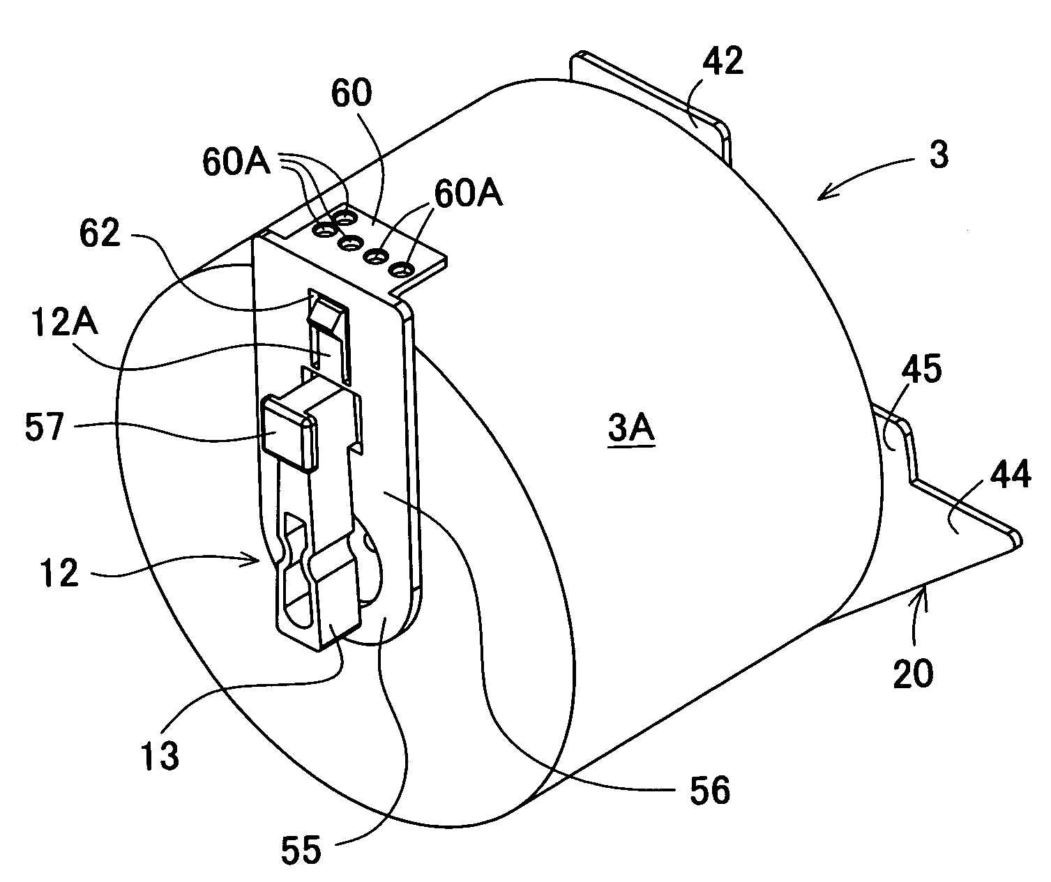
[0043] As shown in FIG. 7A, a feeding motor 119 in a conventional printer is driven at a fixed maximum drive current 122 to feed any rolled printing mediums 3A different in width. In FIG. 7B, the feeding motor 119 in the first embodiment is driven at a drive current 122 appropriate to each width of the rolled printing mediums 3A to feed each rolled printing medium 3A. As the result of the measurement, it has been found that the lower drive current 122 is applied to the feeding motor 119 for the wider rolled printing medium 3A, so that a power peak of the printer 1 (the total sum of the drive current 122 to the motor 119 and the average current to a line thermal head 31) is largely reduced. This is because a frictional force between the line thermal head 31 and a platen roller 26 is lowered as the rolled printing medium 3A is wider. This makes it possible to minimize the capacity of power supply of the printer 1, reduce the cost, and downsize the printer 1. Further, the reduction in ...

second embodiment

[0081] As described in detail as above, the printer 201 in the second embodiment comprises the printing medium discrimination sensors S1 to S5 to read information about the drive current 122 from the rolled printing medium 3A, and the control circuit 110 to adjust the drive current 122 to be applied to the feeding motor 119 according to the information about the drive current 122 for the rolled printing medium 3A. Accordingly, the printer drives the feeding motor 119 with the drive current 122 appropriate to each width of the rolled printing mediums 3A, so that the printer can avoid a waste of the power consumption caused due to driving the feeding motor 119 by the maximum drive current 122 regardless of the width of the rolled printing medium 3A. Further, the printer can provide uniform printing quality of the rolled printing mediums 3A of any width. Furthermore, the information of the drive current 122 is directly read from the rolled printing medium 3A, so that the mismatch betwe...


PUM


Abstract

A printer capable of printing with high quality by driving the drive motor according to information about a drive current to be applied to a drive motor of a platen roller to feed the printing medium, each of which has the information. Accordingly, the printer comprises the printing medium discrimination sensors to read information about the drive current from the printing medium and the control circuit to adjust the drive current to be applied to the feeding motor according to the information about the drive current for the printing medium.

Description

BACKGROUND OF THE INVENTION [0001] 1. Field of the Invention [0002] The present invention relates to a printer to print on a printing medium which has been fed, especially relates to controlling a drive current to feed the printing medium. [0003] 2. Description of Related Art [0004] Conventionally, there has been widely used a printer which is arranged to operate predetermined printing on a printing medium with a line thermal head, while the printer feeds the printing medium by a printing medium feeding part of a platen. The printing medium may include rolled printing mediums of various widths for thermal printing, each of which is directly mountable in the printer, and a rolled printing medium with a thermal ink ribbon set in a dedicated holder. [0005] A drive current to drive the platen has been generally set high, considering the various widths of the printing mediums to be used. Accordingly, the drive current to drive the platen becomes excessive depending on the widths of the p...

Claims


Application Information

Patent Timeline
IPC IPC(8): B41J29/38B41J15/04B41J15/06
CPCB41J11/46
Inventor UNOTORO, HIROTSUGU
Owner BROTHER KOGYO KK
Why Eureka
Try Eureka