
Hammer having enhanced strength

Inactive Publication Date: 2006-04-06
CHEN JOHN
View PDF9 Cites 3 Cited by
  • Summary
  • Abstract
  • Description
  • Claims
  • Application Information

AI Technical Summary

Benefits of technology

[0006] The primary objective of the present invention is to provide a hammer having an enhanced strength.
[0008] A further objective of the present invention is to provide a hammer, wherein the protective jacket of the handle encompasses a periphery of the combination bar and the mediate portion of the hammer body entirely, so that the handle and the hammer body are combined with each other rigidly and stably, thereby enhancing the combination strength of the hammer.
[0009] A further objective of the present invention is to provide a hammer, wherein the shock-absorbing hole of the hammer body provides a shock-absorbing effect so that the reaction from the striking portion of the hammer body is reduced largely to reduce the impact transmitted from the striking portion of the hammer body to the handle, thereby preventing the reaction from vibrating or injuring a user's wrist.
[0010] A further objective of the present invention is to provide a hammer, wherein the shock-absorbing hole of the hammer body provides a shock-absorbing effect to suppress the vibration during the striking process of the hammer, so that the user can operate the hammer in a comfortable manner, thereby enhancing the striking efficiency of the hammer.
[0011] A further objective of the present invention is to provide a hammer, wherein the shock-absorbing hole of the hammer body reduces the required material of the hammer, thereby decreasing costs of fabrication of the hammer.
[0012] A further objective of the present invention is to provide a hammer, wherein the shock-absorbing hole enhances space of deformation of the hammer body during the hardening treatment, thereby enhancing the working efficiency of the hammer.

Problems solved by technology

However, when the striking portion of the hammer hits a workpiece, such as a nail or the like, the vibration applied by the workpiece on the striking portion is directly transmitted through the head and the handle to a user's one hand, so that the user easily feels uncomfortable, thereby causing inconvenience to the user during operation of the conventional hammer.
In addition, the head and the handle are not combined with each other rigidly and stably, thereby greatly decreasing the combination strength of the conventional hammer.

Method used


Image

  • Hammer having enhanced strength
  • Hammer having enhanced strength
  • Hammer having enhanced strength

Examples


Embodiment Construction

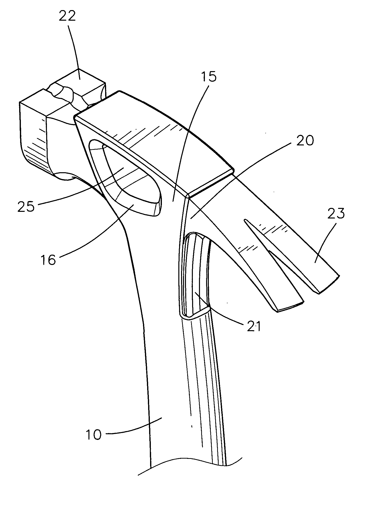
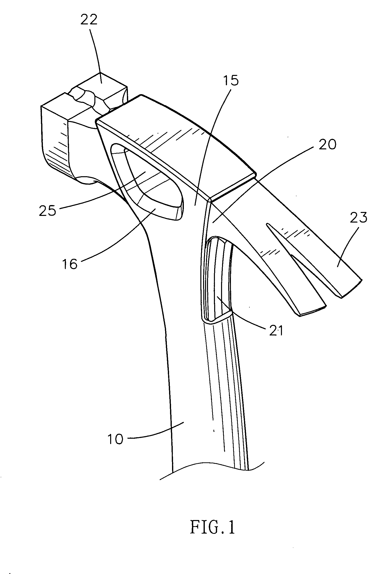
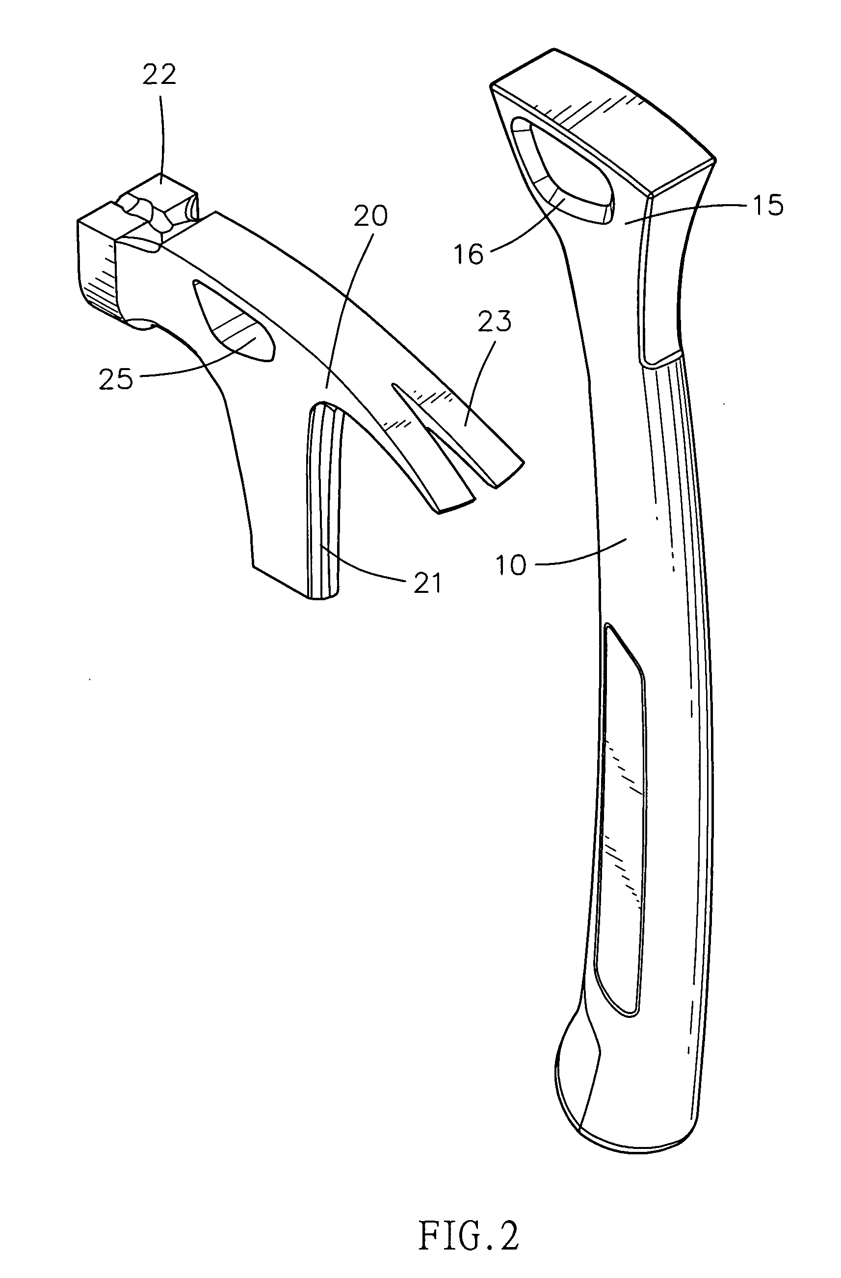
[0023] Referring to the drawings and initially to FIGS. 1-4, a hammer in accordance with the preferred embodiment of the present invention comprises a handle 10, and a hammer body 20 mounted on an end of the handle 10.

[0024] The hammer body 20 is perpendicular to the handle 10 and has a first end formed with a striking portion 22, a mediate portion formed with a shock-absorbing hole 25 and a second end formed with a nail pull portion 23. The hammer body 20 has a side formed with a combination bar 21 extended downward and inserted into a hollow inside of the handle 10. The combination bar 21 of the hammer body 20 is located at the mediate portion of the hammer body 20.

[0025] The shock-absorbing hole 25 of the hammer body 20 has an axis perpendicular to a force line of the hammer body 20 as shown in FIG. 3. The shock-absorbing hole 25 of the hammer body 20 is extended through two opposite sides of the hammer body 20. The shock-absorbing hole 25 of the hammer body 20 is located at a ...


PUM


Abstract

A hammer includes a handle, a hammer body mounted on an end of the handle and having a side formed with a combination bar inserted into the handle, and a protective jacket integrally formed on the handle to encompass a periphery of the combination bar and a mediate portion of the hammer body entirely. Thus, the protective jacket of the handle encompasses the periphery of the combination bar and the mediate portion of the hammer body entirely, so that the handle and the hammer body are combined with each other rigidly and stably, thereby enhancing the combination strength of the hammer.

Description

BACKGROUND OF THE INVENTION [0001] 1. Field of the Invention [0002] The present invention relates to a hammer, and more particularly to a hammer having an enhanced strength. [0003] 2. Description of the Related Art [0004] A conventional hammer comprises a handle, a head mounted on a first end of the handle, a striking portion integrally formed on a distal end of the head, and a grip mounted on a second end of the handle. However, when the striking portion of the hammer hits a workpiece, such as a nail or the like, the vibration applied by the workpiece on the striking portion is directly transmitted through the head and the handle to a user's one hand, so that the user easily feels uncomfortable, thereby causing inconvenience to the user during operation of the conventional hammer. In addition, the head and the handle are not combined with each other rigidly and stably, thereby greatly decreasing the combination strength of the conventional hammer. SUMMARY OF THE INVENTION [0005] Th...

Claims


Application Information

Patent Timeline
IPC IPC(8): B25D1/00B25D1/12
CPCB25D1/12B25G3/34
Inventor CHEN, JOHN
Owner CHEN JOHN
Learn More