Apparatus for charging and removing load carriers or piece goods

a technology for loading and removing load carriers, applied in the direction of conveyor parts, storage devices, mechanical conveyors, etc., can solve the problem of large cost factor, and achieve the effect of economic, simple and functional charging and/or removal

Inactive Publication Date: 2006-04-06
SIEMENS AG
View PDF4 Cites 29 Cited by
  • Summary
  • Abstract
  • Description
  • Claims
  • Application Information

AI Technical Summary

Benefits of technology

[0004] The present invention is based on the object of providing an

Problems solved by technology

These devices, because they have to be assigned

Method used


Image

  • Apparatus for charging and removing load carriers or piece goods
  • Apparatus for charging and removing load carriers or piece goods
  • Apparatus for charging and removing load carriers or piece goods

Examples


Embodiment Construction

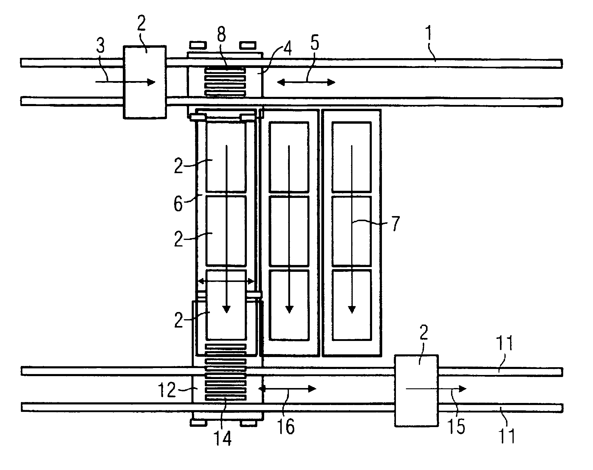
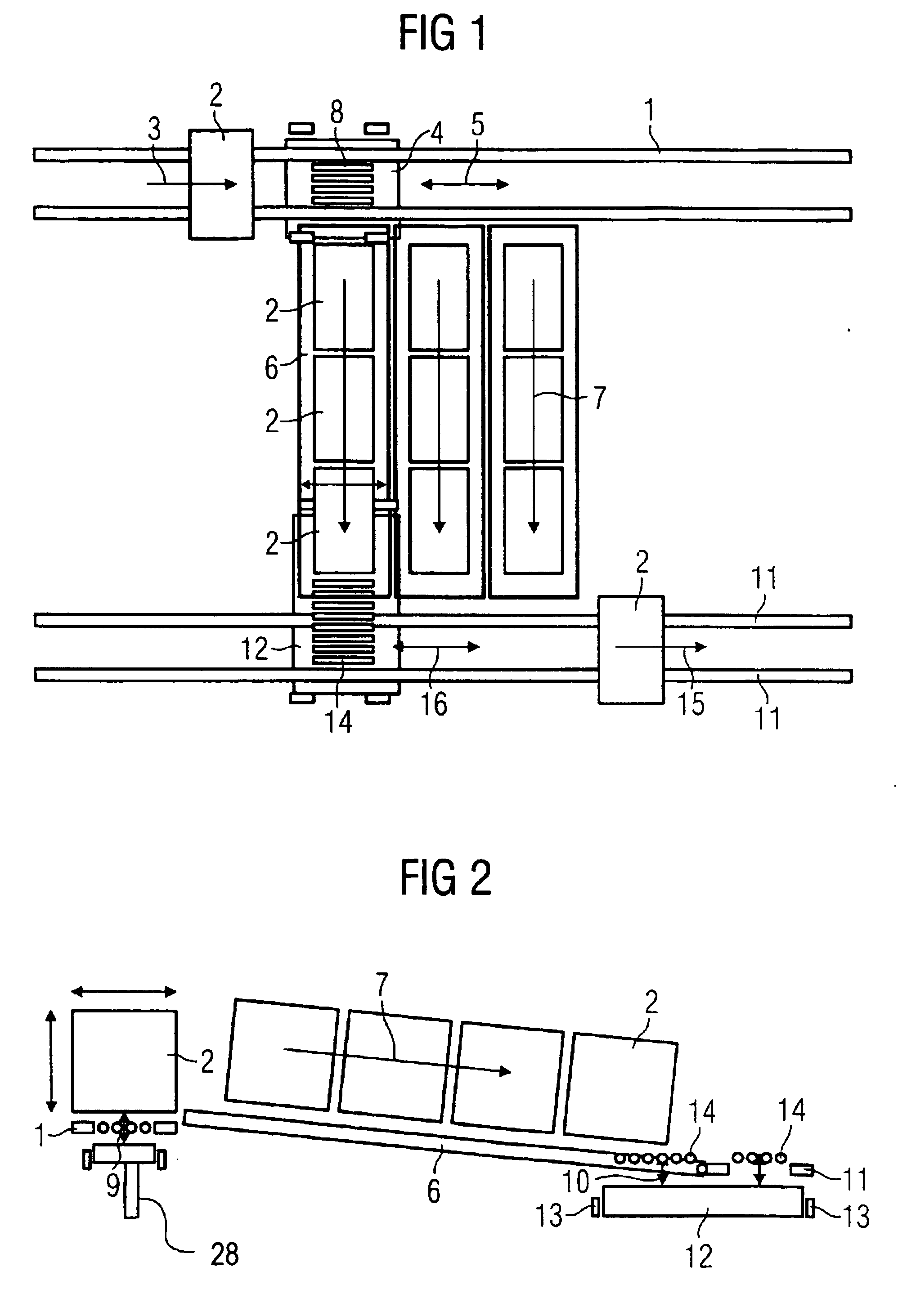
[0028] In FIG. 1, a feed conveyor in the form of a belt or chain conveyor is designated 1, on which the load 2, which can be a piece of goods itself or a load carrier, is conveyed up in the transport direction 3. Below the level of the feed conveyor 1, the mobile carriage 4 is arranged such that it can be moved freely in both transport directions 5 and, in the illustration of FIG. 1, has been stopped in a position in which the mobile carriage 4 is located opposite one of the buffer sections 6. This buffer section in the present example is intended to represent a sloping roller track, on which a number of loads 2 have already been buffeted. The buffer section 6 is inclined in the direction of arrow 7, such that, following the transfer from the mobile carriage 4 onto the buffer section, the loads 2 move downward as a result of gravity.

[0029] On the mobile carriage 4, the transfer element 8 is arranged in the form of a transverse conveyor, which is constructed as a roller conveyor. As...


PUM


Abstract

The invention relates to an apparatus for charging and/or removing load carriers or piece goods onto or from buffer sections, such as sloping roller tracks or continuous channels, by means of a transfer apparatus for picking up in each case one load carrier or item of piece goods from a conveyor track and discharging it to a fixed buffer section, or for accepting a load carrier or item of piece goods from a buffer section in order to pass it on to a fixed discharge location. In order to achieve the object of providing an economic, simple and functional charging and/or removal apparatus, it is proposed to construct the transfer apparatus as a mobile carriage which can be positioned below the transport plane of the conveyor track or the buffer section and has a transfer element arranged thereon, and to configure the mobile carriage such that it can be moved transversely with respect to the buffer sections into positions in which it corresponds with one of the buffer sections in each case.

Description

BACKGROUND AND FIELD OF THE INVENTION [0001] The invention relates to an apparatus for charging and / or removing load carriers or piece goods onto or from buffer sections, such as sloping roller tracks or continuous channels, by means of a transfer apparatus for picking up in each case one load carrier or item of piece goods from a conveyor track and discharging it to a fixed buffer section, or for accepting a load carrier or item of piece goods from a buffer section in order to pass it on to a fixed discharge location. [0002] The withdrawal or removal of load carriers or piece goods from driven or passive buffer sections, such as continuous channels or sloping roller tracks, in order to transfer the load buffered there to a haul-off belt at the end of the buffer section is normally carried out with devices of which in each case one is assigned to each continuous channel or each sloping roller track. For example, unblocking devices similar to an opening barrier or removal devices in ...

Claims


Application Information

Patent Timeline
IPC IPC(8): B65G1/00
CPCB65G1/0492B65G1/08B65G47/53
Inventor BESCH, AXELSUESS, HEIKO
Owner SIEMENS AG
Why Eureka
Try Eureka