Self retaining sliding bar interlock for circuit breaker

a technology of circuit breakers and sliding bars, which is applied in the direction of electric switches, emergency protective devices, electrical equipment, etc., can solve problems such as step difficulty

Inactive Publication Date: 2006-04-06
EATON CORP
View PDF4 Cites 20 Cited by
  • Summary
  • Abstract
  • Description
  • Claims
  • Application Information

AI Technical Summary

Benefits of technology

[0009] These needs, and others, are addressed by the present invention which provides an interlock mechanism for preventing a first circuit breaker having a first actuating mechanism and a second circuit breaker having a second actuating mechanism from simultaneously being in a closed condition. The interlock mechanism includes a frame, a sliding bar slideably mounted within the frame, and one or more retaining protrusions extending outwardly from one or more inner edges of the frame. The sliding bar is movable between a first position and a second position. In the first position the sliding bar blocks a path of movement of the first actuating mechanism and in the second position the sliding bar blocks a path of movement of the second actuating mechanism. The one or more retaining protrusions frictionally engage the sliding bar when the sliding bar is in the first position and hold it in place. The one or more retaining protrusions preferably frictionally engage the sliding bar with a frictional force sufficient to resist the force of gravity. The sliding bar may be generally T-shaped and include a handle portion, a first blocking portion connected to a first side of the handle portion, and a second blocking portion connected to a second side of the handle portion opposite the first side of the handle portion.
[0010] In one embodiment, the first and second circuit breakers are arranged in a vertic...

Problems solved by technology

These steps are made difficult by the fact that gravity will force the sliding bar downward if not held in place by the ...

Method used


Image

  • Self retaining sliding bar interlock for circuit breaker
  • Self retaining sliding bar interlock for circuit breaker
  • Self retaining sliding bar interlock for circuit breaker

Examples


Embodiment Construction

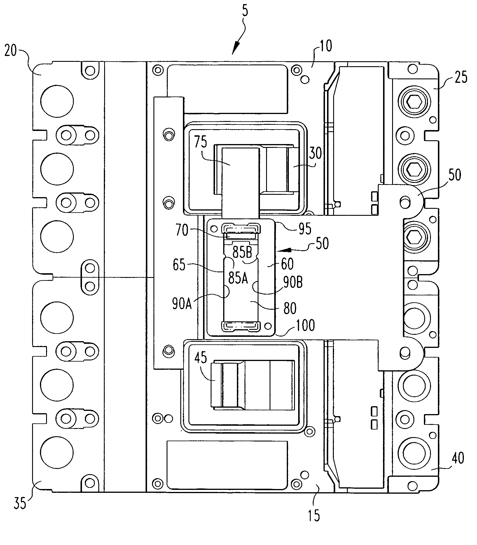
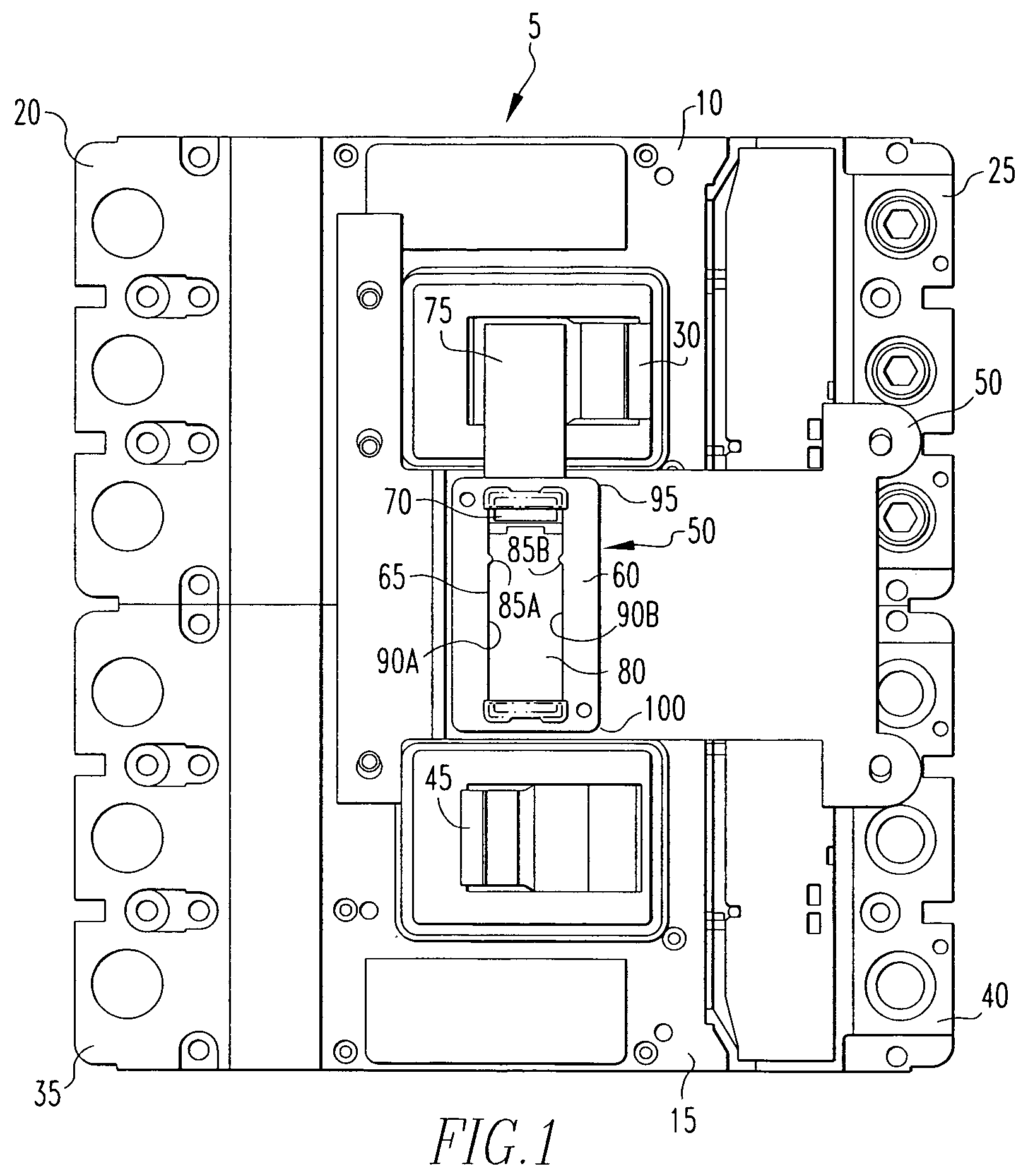
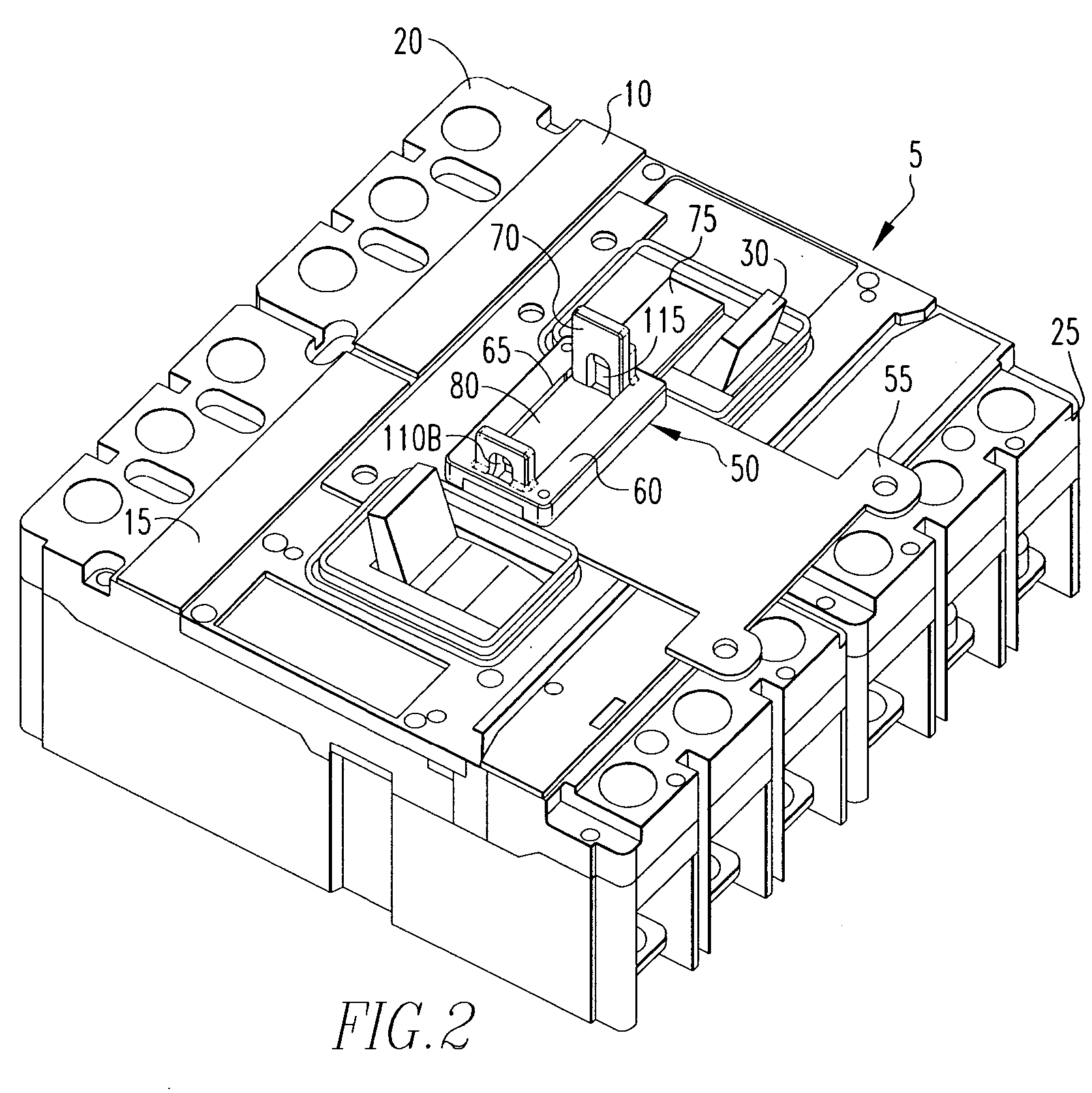
[0017]FIG. 1 is a front elevational view and FIG. 2 is an isometric view of a circuit breaker assembly 5 according to the present invention. Circuit breaker assembly 5 includes circuit breaker 10 and circuit breaker 15. As seen in FIGS. 1 and 2, circuit breaker 10 and circuit breaker 15 are mounted in a vertical relationship with respect to one another wherein circuit breaker 10 is mounted and stacked above circuit breaker 15 such that the gravitational force applied to circuit breaker assembly 5 is as shown by the arrow in FIG. 1.

[0018] Circuit breaker 10 has a line side 20 having terminals for connecting to a power source and a load side 25 having terminals for connecting to a load. Circuit breaker 10 also has an operating handle 30 that is movable in an arcuate path in a horizontal direction that is generally perpendicular to the gravitational force shown by the arrow in FIG. 1. Operating handle 30 is movable from a closed position adjacent to line side 20 to an open position ad...


PUM


Abstract

An interlock mechanism for preventing a first circuit breaker having a first actuating mechanism and a second circuit breaker having a second actuating mechanism from simultaneously being in a closed condition. The interlock mechanism includes a frame, a sliding bar slideably mounted within the frame, and one or more retaining protrusions extending outwardly from one or more inner edges of the frame. The sliding bar is movable between a first position and a second position. In the first position the sliding bar blocks a path of movement of the first actuating mechanism and in the second position the sliding bar blocks a path of movement of the second actuating mechanism. The one or more retaining protrusions frictionally engage the sliding bar when the sliding bar is in the first position and holds it in place, preferably with a frictional force sufficient to resist the force of gravity and/or vibrations.

Description

CROSS-REFERENCE TO RELATED APPLICATION [0001] This application claims the benefit of U.S. Provisional Application No. 60 / 615,124 entitled “Self Retaining Sliding Bar Interlock For Circuit Breaker,” which was filed on Oct. 1, 2004.BACKGROUND OF THE INVENTION [0002] 1. Field of the Invention [0003] This invention relates to an interlock assembly for a pair of circuit breakers and, more specifically, to an interlock assembly having a self retaining sliding bar mechanism which allows an operator to use both hands to toggle the breaker. [0004] 2. Background Information [0005] There are a number of applications where it is required that the operation of two circuit breakers be coordinated such that only one circuit breaker can be in the closed, operating position at one time. For example, the operation of two circuit breakers must be coordinated when providing a power-consuming load with electrical power from either of two different sources, such as a commercial power system and an auxili...

Claims


Application Information

Patent Timeline
IPC IPC(8): H01H9/28
CPCH01H9/22H01H9/26H01H9/282H01H2300/018
Inventor BOGDON, ERIK RUSSELLFODI, VICKI DIANEBRAND, RONALD WILLIAMGULA, LANCEMARTELLI, DOMINIC PATRICKTRAX, JAMES ALAN
Owner EATON CORP
Why Eureka
Try Eureka