
Memory efficient interleaving

a technology of memory and interleaving, applied in the field of memory efficient interleaving, can solve the problems of corrupted data that is transmitted over a channel from one electronic device (transmitting device) to another electronic device (receiving device), not enough good data around and not enough good data in between the bad data to correct the bad data

Inactive Publication Date: 2006-04-06
SONY CORP +1
View PDF8 Cites 3 Cited by
  • Summary
  • Abstract
  • Description
  • Claims
  • Application Information

AI Technical Summary

Benefits of technology

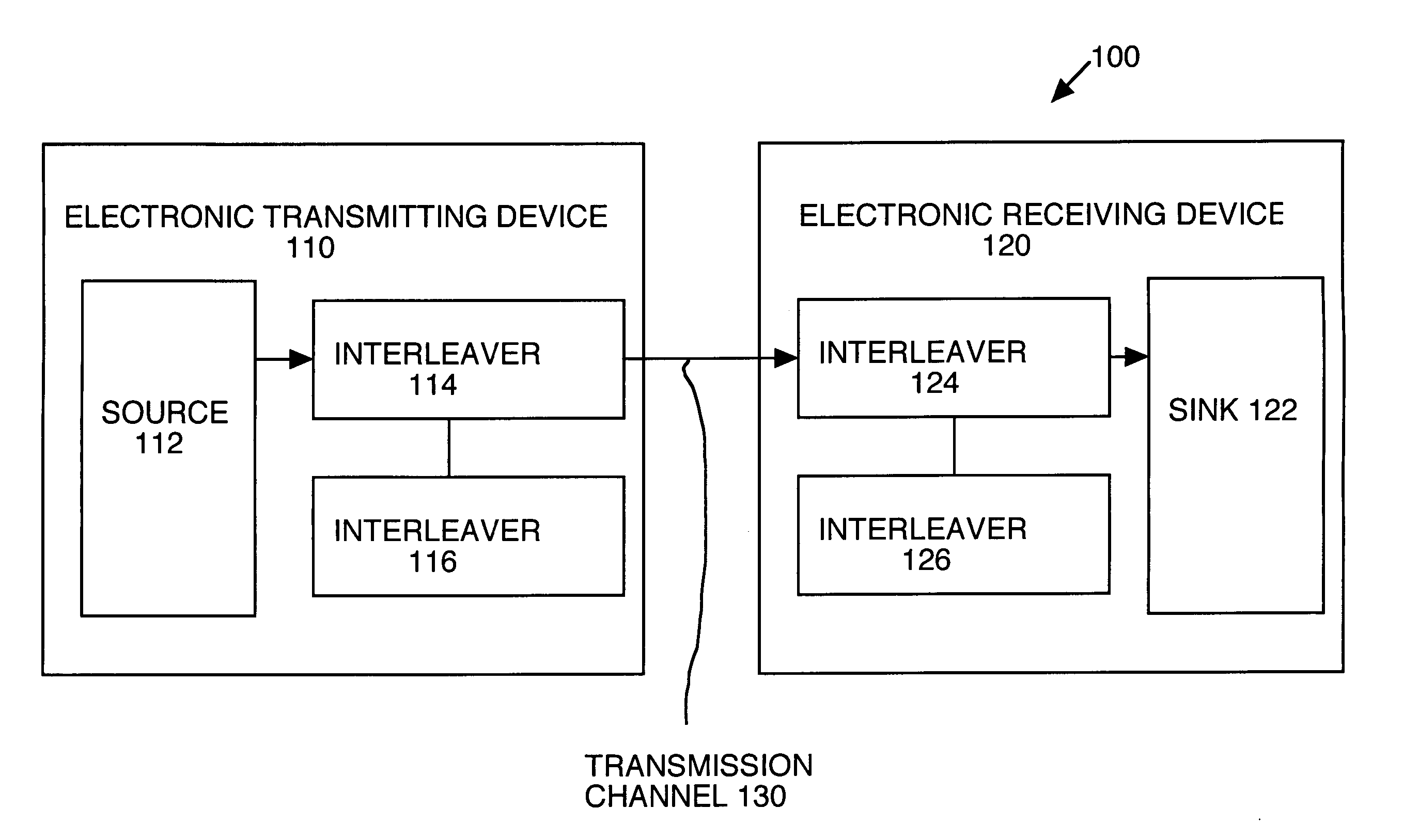
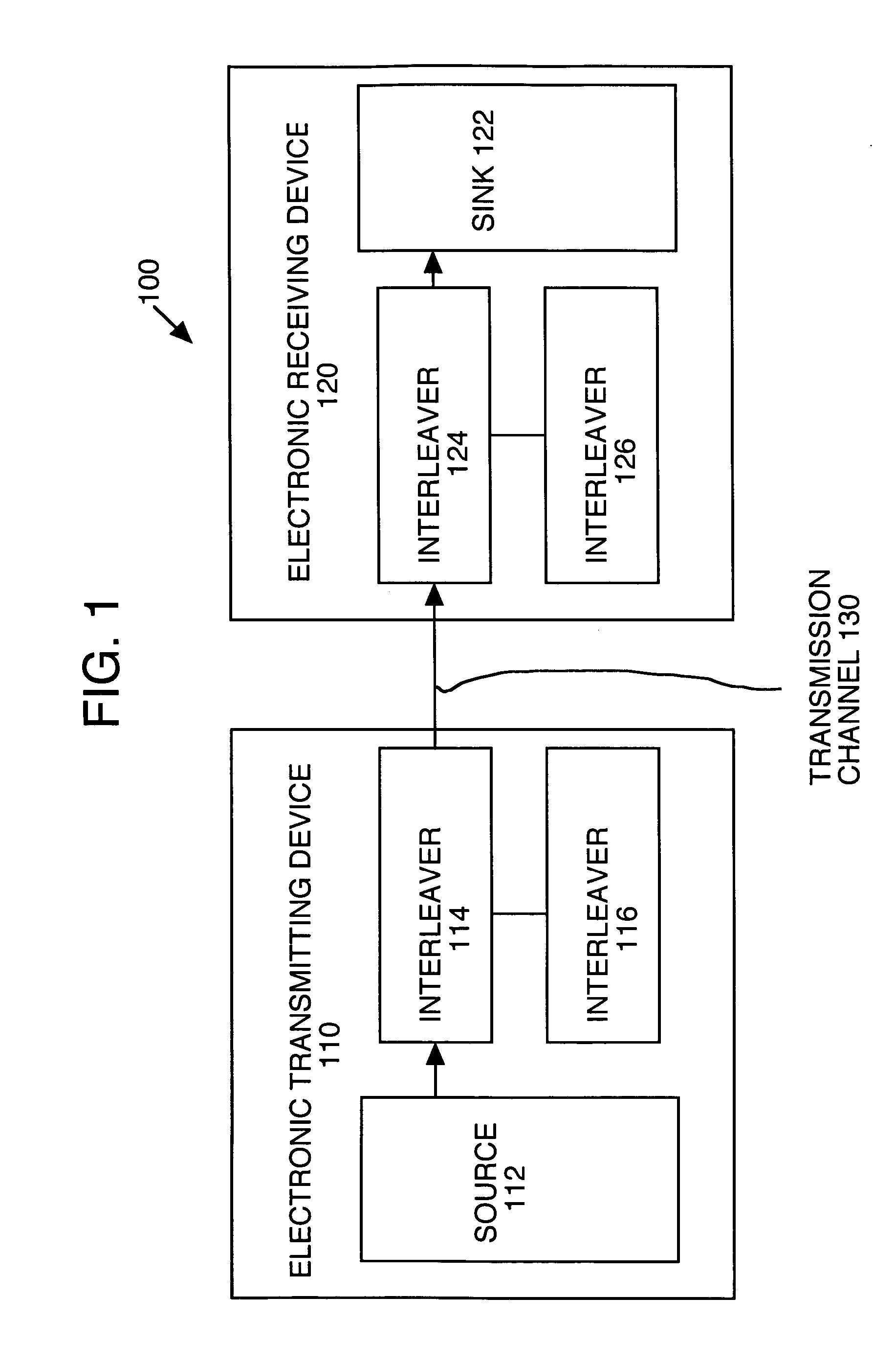
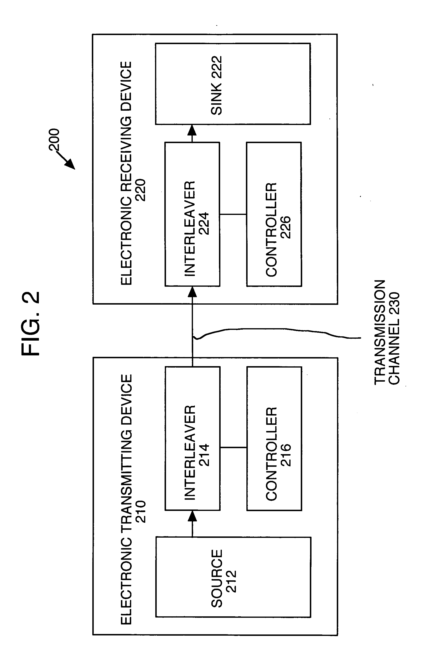
The present invention provides a method and system for efficient memory usage in interleaving. This is achieved by using a single interleaver to read and write symbols from different symbol sets. A controller synchronizes the reading and writing of symbols so that a particular symbol of the second set is only written to a vacant location after a particular symbol of the first set has been read. This helps to conserve memory resources. The controller can switch between different orders, such as row and column order, to optimize the use of memory space. Overall, this invention allows for efficient use of memory in interleaving.

Problems solved by technology

Frequently data that is transmitted over a channel from one electronic device (transmitting device) to another electronic device (receiving device) is corrupted, for example, due to channel impairments, such as noise, fading and jamming.
However, if a sufficient number of errors occur within a relatively short period of time, there may not be enough good data around the bad data to correct the bad data.
For example, if a device receives a data stream, such as “A B C X X X G H I J K L,” where several symbols which are received in a short time span are in error, then there may not be enough good data in between the bad data to correct the bad data.
Memory is expensive and a considerable amount of memory is needed for implementing interleavers in real-time systems, such as video systems.

Method used


Image

  • Memory efficient interleaving
  • Memory efficient interleaving
  • Memory efficient interleaving

Examples


Embodiment Construction

[0020] Reference will now be made in detail to the preferred embodiments of the present invention, a method and system are described for implementing memory efficient interleaving, examples of which are illustrated in the accompanying drawings. While the invention will be described in conjunction with the preferred embodiments, it will be understood that they are not intended to limit the invention to these embodiments. On the contrary, the invention is intended to cover alternatives, modifications and equivalents, which may be included within the spirit and scope of the invention as defined by the appended claims. Furthermore, in the following detailed description of the present invention, numerous specific details are set forth in order to provide a thorough understanding of the present invention. However, it will be recognized by one of ordinary skill in the art that the present invention may be practiced without these specific details. In other instances, well-known methods, pro...


PUM


Abstract

A method and system using a single interleaver at a either a receiving device or a transmitting device where a first symbol set is read from the single interleaver and concurrently with a second symbol set is written to the single interleaver, and a controller that synchronizes the reading of the first symbol set from the interleaver and the writing of the second symbol set to the interleaver so that a particular symbol of the second symbol set is only written to a location of the interleaver after a particular symbol of the first symbol set has been read from the location. The controller may switch between orders, e.g., row order and column order, of reading and / or writing symbols to the single interleaver when all of the symbols for a particular set of symbols associated with the single interleaver have been read, according to another embodiment.

Description

BACKGROUND OF THE INVENTION [0001] 1. Field of the Invention [0002] Embodiments of the present invention relate to the field of digital communication systems. More specifically, embodiments of the present invention relate to implementing interleavers and de-interleavers in a memory efficient manner. [0003] 2. Related Art [0004] Frequently data that is transmitted over a channel from one electronic device (transmitting device) to another electronic device (receiving device) is corrupted, for example, due to channel impairments, such as noise, fading and jamming. Various methods, such as forward error correction (FEC), have been developed to correct the errors in the data at the receiving device (a classical example of FEC is the Reed-Solomon encoder / decoder). In one approach, FEC uses error free data around the bad data to correct the bad data. For example, the transmitting device may transmit a data stream of symbols “A B C D E F G H I J K L” to a receiving device. For the purposes ...

Claims


Application Information

Patent Timeline
Patent Type & Authority Applications(United States)
IPC IPC(8): H03M1/12
CPCH04L1/0071
Inventor CHAMPION, MARK
Owner SONY CORP
Learn More