Image display apparatus and image display system
a technology of image display and image display, applied in the field of image display apparatus, can solve problems such as fatigu
- Summary
- Abstract
- Description
- Claims
- Application Information
AI Technical Summary
Problems solved by technology
Method used
Image

Examples
embodiment 1
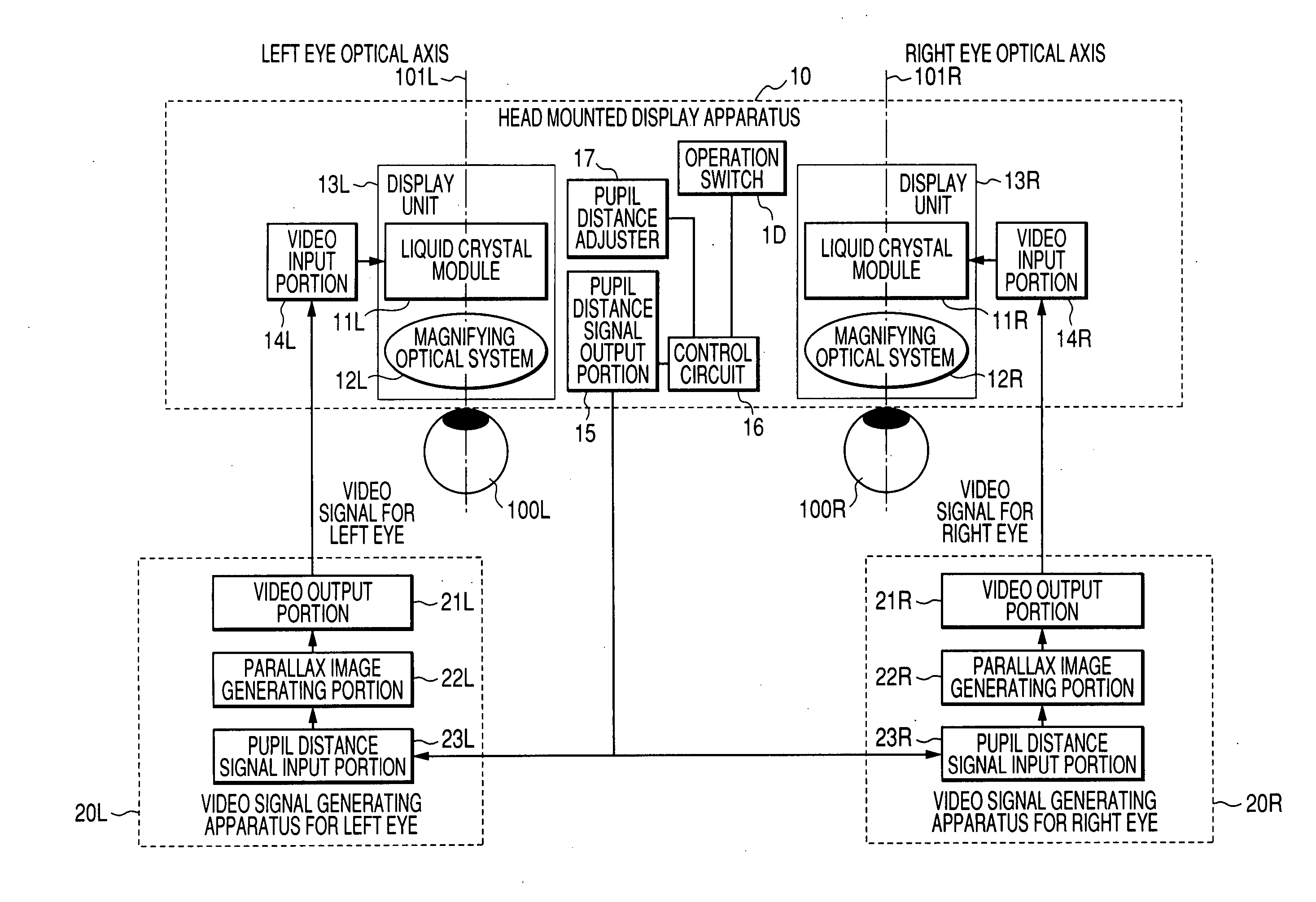
[0020]FIG. 1 is a block diagram showing a configuration of an image display system having a head mounted display apparatus being Embodiment 1 of the present invention, and a video signal generating apparatus for outputting video signals to the head mounted display apparatus.
[0021] The head mounted display apparatus 10 has display units 13R and 13L for a right eye 100R and for a left eye 100L, an interpupillary distance adjuster (interval changing portion) 17, an interpupillary distance signal output portion (signal output means) 15, video input portions 14R and 14L, a control circuit (a circuit using a microcomputer etc.) 16 and an operation switch 1D.
[0022] The display units 13R and 13L respectively have liquid crystal modules (image forming elements) 11R and 11L as display devices and magnifying optical systems (first and second optical units) 12R and 12L of magnifying the displayed images in the liquid crystal modules 11R and 11L.
[0023] The magnifying optical systems 12R and 1...
embodiment 2
[0051]FIG. 5 shows a configuration of an image display system being Embodiment 2 of the present invention. In FIG. 5, like reference numerals designate the same members as the members described in Embodiment 1, and detailed descriptions will be omitted.
[0052] A head mounted display apparatus in an image display system of the present embodiment relates to Mixed Reality and is a head mounted display apparatus of a video see-through type which has an image taking optical system and a display optical system.
[0053] The head mounted display apparatus 40 of the present embodiment has image pickup units (first and second image pickup means) 18R and 18L as well as taken image output portions 1CR and 1CL in addition to the configuration of a head mounted display apparatus of Embodiment 1.
[0054] The image pickup units 18R and 18L respectively have image pickup elements 19R and 19L such as a CMOS sensor and a CCD sensor, drive circuits (not shown) for driving image pickup elements 19R and 19...
embodiment 3
[0067]FIG. 6 shows a configuration of an image display system being Embodiment 3 of the present invention. In FIG. 6, like reference numerals designate the same members as the members described in Embodiments 1 and 2, and detailed descriptions will be omitted.
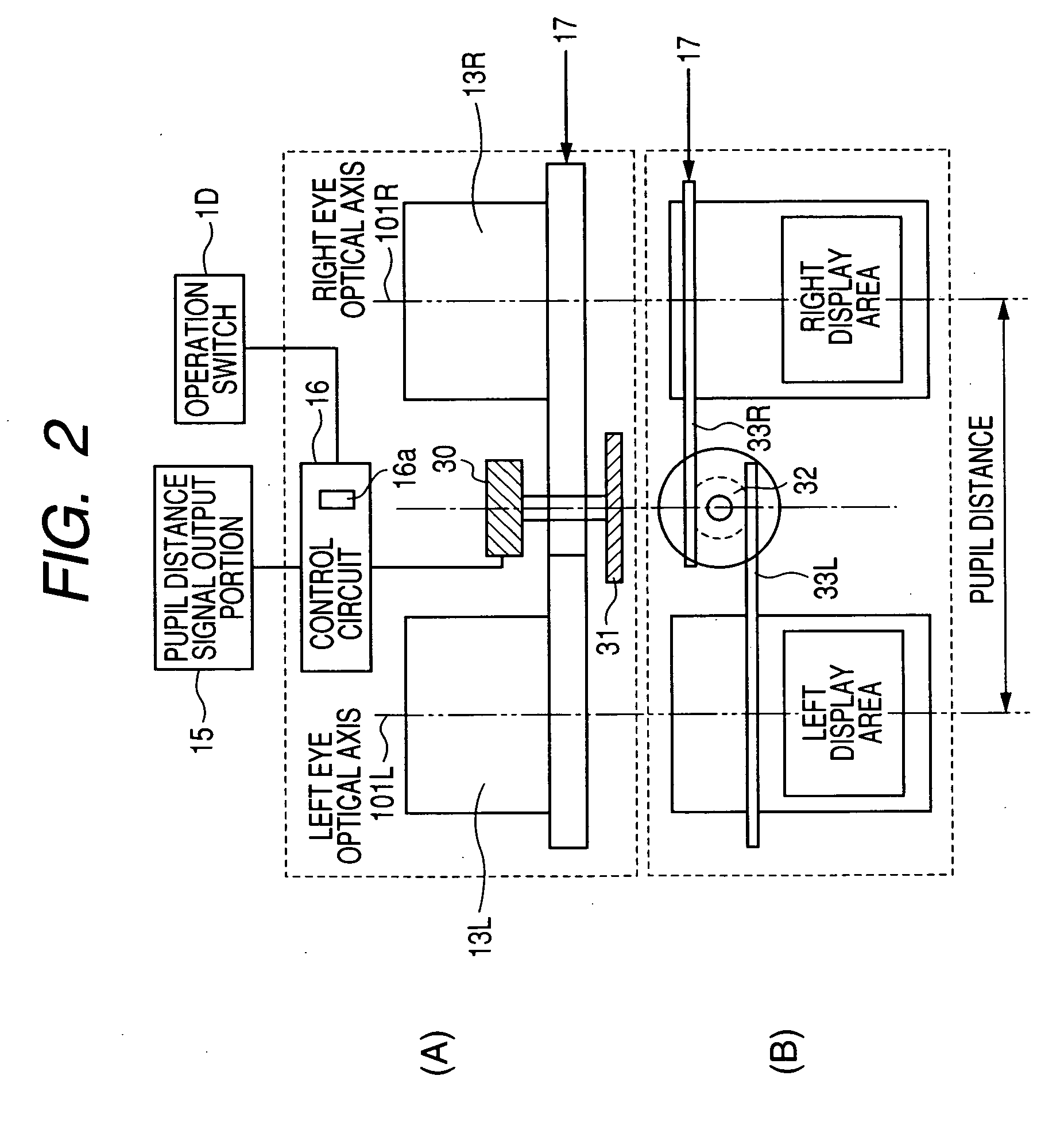
[0068] In Embodiments 1 and 2, a wearer operates an interpupillary distance adjuster so as to adjust the interpupillary distance at the head mounted display apparatus. On the other hand, a head mounted display apparatus 60 in the present embodiment detects wearer's interpupillary distance so as to adjust the interpupillary distance at the head mounted display apparatus 60 automatically based on this detected outcome.
[0069] In addition to the configuration of a head mounted display apparatus of Embodiment 2, the head mounted display apparatus 60 of the present embodiment has a pupil detecting unit (interpupillary distance detecting means) 1B for detecting wearer's pupil positions. The pupil detecting unit 1B can be configured ...
PUM
 Abstract
Description
Claims
Application Information
 - Generate Ideas
- Intellectual Property
- Life Sciences
- Materials
- Tech Scout
- Unparalleled Data Quality
- Higher Quality Content
- 60% Fewer Hallucinations
Browse by: Latest US Patents, China's latest patents, Technical Efficacy Thesaurus, Application Domain, Technology Topic, Popular Technical Reports.
© 2025 PatSnap. All rights reserved.Legal|Privacy policy|Modern Slavery Act Transparency Statement|Sitemap|About US| Contact US: help@patsnap.com