Chaotic communication system and method using modulation of nonreactive circuit elements

a communication system and non-reactive circuit technology, applied in the field of information transmission techniques, can solve the problems of a general limited modulation bandwidth available when using such techniques, and a certain amount of settling tim

Inactive Publication Date: 2006-04-06
LEIDOS
View PDF16 Cites 79 Cited by
  • Summary
  • Abstract
  • Description
  • Claims
  • Application Information

AI Technical Summary

Problems solved by technology

The modulation bandwidth available when using such techniques, however, has been determined to be generally limited to 10 to 15% of the tank circuit frequency in the transmitting circuit.
This limitation is believed to be due to the fact that changing lump parameters in the transmitter causes a certain amount of settling time before the receiver can synchronize with the changed transmitter parameters.

Method used


Image

  • Chaotic communication system and method using modulation of nonreactive circuit elements
  • Chaotic communication system and method using modulation of nonreactive circuit elements
  • Chaotic communication system and method using modulation of nonreactive circuit elements

Examples


embodiments

(First-Generation Embodiments)

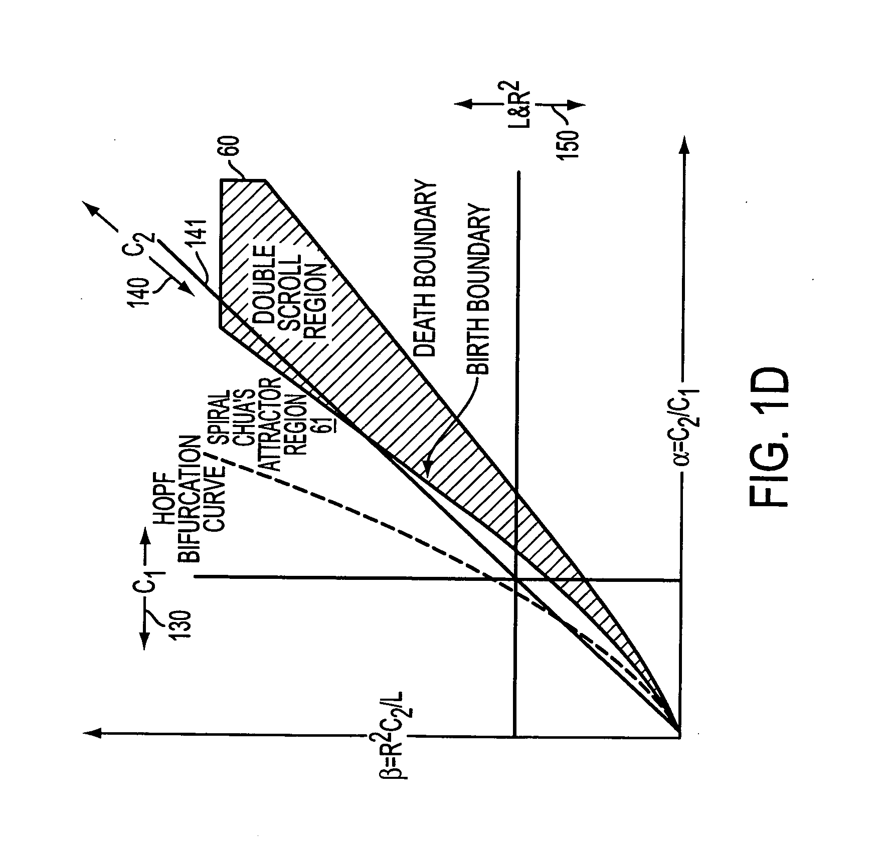
[0141] Referring again to FIG. 1D, discussed above, the various chaotic oscillating regimes of the Chua circuit are mapped onto an α / β parameter plane. Circuits falling in a double scroll region 60 are characterized by oscillation about two strange attractor equilibrium points (“double scroll”). Circuits falling in a spiral set of oscillating regimes 61 exhibit oscillation about only one strange attractor equilibrium point (“single scroll”).

[0142] The oscillations of a circuit operating in a single-scroll attractor mode can be seen graphically in FIG. 22A, which plots two voltages V1 and V2 as a function of time for a transmitter without modulation. The two voltages are measured at points 242 and 282, respectively, as shown in one embodiment of FIG. 2A. (In this example, V2 is measured at the L-C tank circuit and V1 is measured at the nonlinear resistance element). While the circuit operates in a non-modulated state, the values of V1 and V2 vary chaoti...


PUM


Abstract

A chaotic communication system employs transmitting and receiving chaotic oscillating circuits. One improvement to first-generation systems is the ability to modulate a nonreactive element in the transmitting circuit, thus increasing modulation bandwidth. Other features include insertion of a gain control amplifier in a chaotic receiver; signal filtering in chaotic transmitters and receivers; use of chaotic modulation techniques for cellular telephony applications; dual-transmitter and receiver systems; a dual receiver synchronization detector; interfaces to communication systems; analog chaotic signal modulation; use of multiple chaotic transmitters and receivers; digital algorithm improvement using a cube-law nonlinear component; a Gb-only receiver; a Gb-only transmitter; and positive slope transmitter and receiver systems.

Description

[0001] This application is a Continuation of commonly-owned U.S. application Ser. No. 09 / 317,124, entitled “Chaotic Communication System and Method Using Modulation of Nonreactive Circuit Elements,” filed on May 24, 1999 which is a continuation-in-part of commonly-owned, copending U.S. application Ser. No. 09 / 116,661, entitled “Communications System Using Chaotic Synchronized Circuits,” filed on Jul. 17, 1998 and naming as inventors Daniel E. Hinton, Sr. and Aaron Budgor. The above-cited applications are incorporated into the body of this application in their entireties.TECHNICAL FIELD [0002] This invention relates generally to information transmission techniques involving modulation and demodulation of a chaotic carrier signal. Many aspects of the invention involve transmitting information by modulating various characteristics of nonreactive circuit elements of a chaotic transmitter. The invention has broad application to communications systems, radar systems and other systems that...

Claims


Application Information

Patent Timeline
Patent Type & Authority Applications(United States)
IPC IPC(8): H04L9/00H04L27/00
CPCH04L27/001
Inventor HINTON, DANIEL E. SR.DEW, NELSON R.LONGTIN, LAURANCE P.GARDNER, CHARLES P.MARTIN, SHANNON W.EDWARDS, MICHAEL C.BERKLEY, ANTWONG L.BOWSER, STEVEN M.
Owner LEIDOS
Why Eureka
Try Eureka