
Security alarm notification using iris detection systems

a technology of iris detection and security alarm, applied in the field of biometric systems, can solve the problems of insecure access control system, inability to detect iris, and inability to set the pre-set code,

Inactive Publication Date: 2006-04-06
HONEYWELL INT INC
View PDF20 Cites 41 Cited by
  • Summary
  • Abstract
  • Description
  • Claims
  • Application Information

AI Technical Summary

Benefits of technology

The present invention is a biometric iris detection system that allows users to set alarm conditions using their eyeball or eyelid. The system can detect the user's blinking pattern or movement patterns to set the alarm condition. The invention provides a convenient and efficient way to set alarm conditions, which can be used in various applications such as security systems or access control.

Problems solved by technology

Providing adequate security for electronic and mechanical systems has rapidly become an important issue in recent years.
Pre-set codes are often forgotten, however, as users have no reliable method of remembering them.
Writing down codes and storing them in close proximity to an access control device (e.g., a combination lock) results in an insecure access control system.
Alternatively, the nuisance of trying several code variations generally renders the access control system more of a problem than a solution.
Password systems are known to suffer from other disadvantages.
Most users, being unsophisticated users of security systems, choose passwords that are relatively insecure.
Unfortunately, passwords and cards have similar drawbacks when utilized for building security, particularly with computer security.
Typically when using a biometric information sample, a low match score results in failure to authorize an individual.
A potential problem with biometrics is the potential that a foe may force an authorized user of biometric-protected systems, buildings and data to gain access to the protected systems, buildings or data.
A breach in security cannot be overcome without further warning once the breach has happened.

Method used


Image

  • Security alarm notification using iris detection systems
  • Security alarm notification using iris detection systems
  • Security alarm notification using iris detection systems

Examples


Embodiment Construction

[0028] Thus, the present invention is not intended to be limited to the embodiments shown or described below, but is to be accorded the widest scope consistent with principles and features disclosed herein. Although preferred embodiments of the present invention are described herein, those skilled in the art can appreciate that a number of varying embodiments can be implemented in accordance with the present invention.

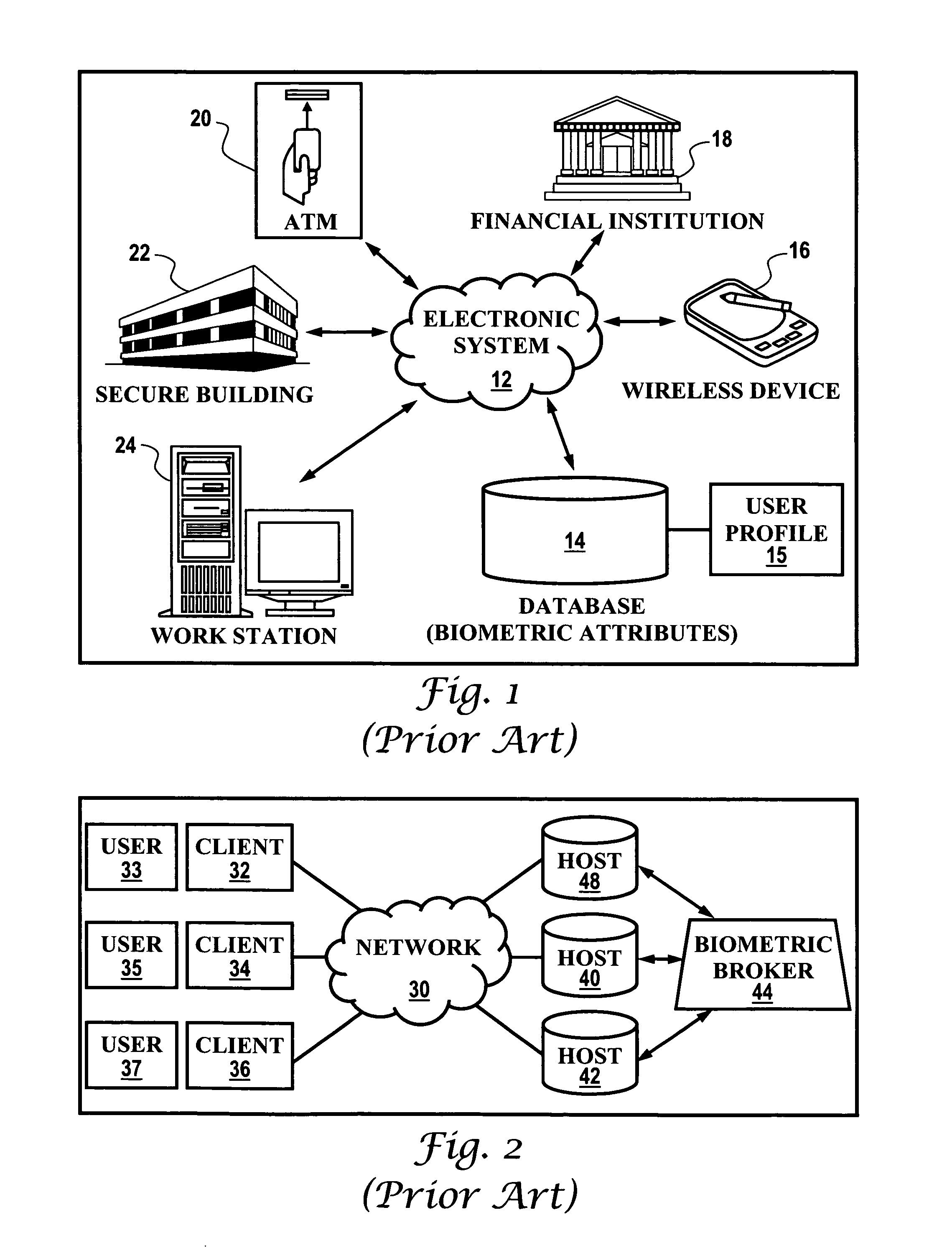
[0029]FIG. 1 illustrates a block diagram of components of an electronic system 12 associated with a database or memory containing biometric attributes 14, in which preferred embodiments of the present invention can be implemented. Database 14 can be linked or integrated with electronic system 12 and can include a at least one user profile 15 containing biometric templates (i.e., samples) of biometric attributes provided previously by particular users. Electronic system 12 can interact with and communicate with a variety of devices and mechanical systems.

[0030] Electr...


PUM


Abstract

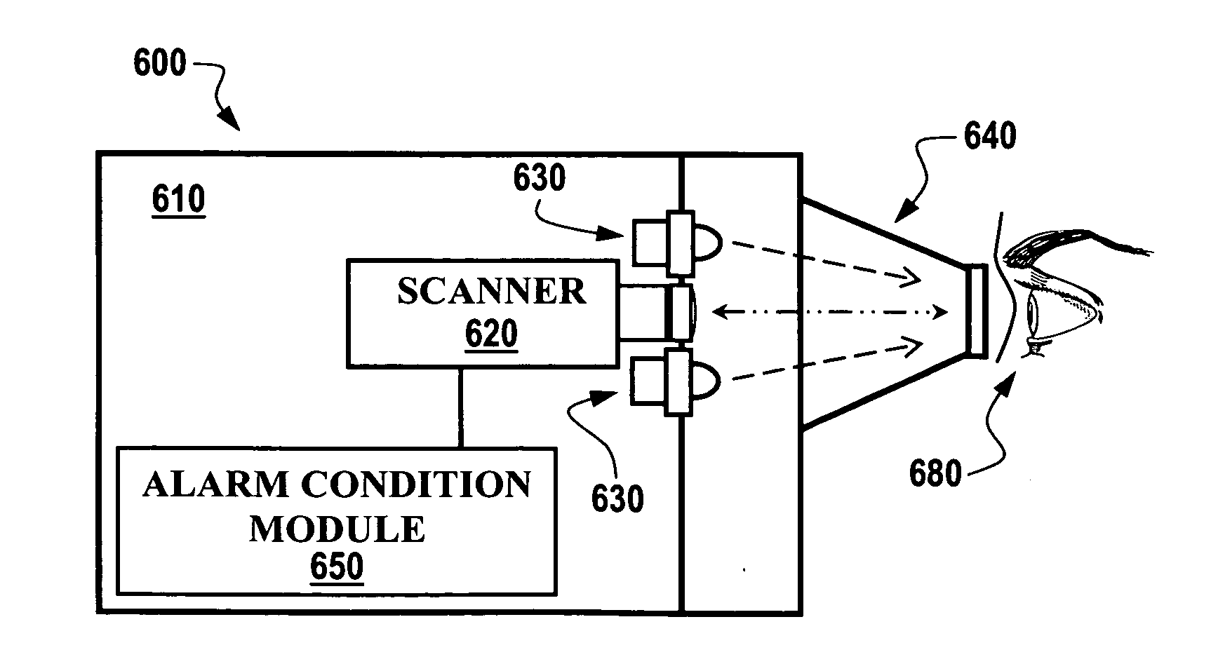
Biometric iris detection systems are adaptable for control of alarm conditions through the systems scanner or reader by physical actions of a user's eye and / or eye lid. An alarm condition can be set in a biometric iris detection system following a predetermined blinking pattern by a user's eyelid. An alarm condition also can be set in a biometric iris detection system following closure of a user's eyelid for a predetermined time following user identification / acceptance by the system. An alarm condition can following a predetermined movement patter of a user's eyeball (e.g., a user looks at a particular area, or areas, within a biometric reader, e.g., upper left, upper right, lower left, lower right, during user identification and acceptance procedures. The embodiments of the present invention can be carried out using biometric iris detection hardware and image processing / control software.

Description

TECHNICAL FIELD [0001] The present invention is generally related to biometric systems. The present invention is also directed to methods of and systems related to biometric iris detection. More particularly, the present invention is related to methods enabling user manipulation of a biometric iris detection system through an iris scanner or reader. BACKGROUND OF THE INVENTION [0002] Providing adequate security for electronic and mechanical systems has rapidly become an important issue in recent years. With the proliferation of computers, computer networks and other electronic device and networks into all aspects of business and daily life, the concern over secure file and transaction access has grown tremendously. The ability to secure data and transactions is particularly important for financial, medical, education, government, military, and communications endeavors. [0003] Using passwords is a common method of providing security for electrical or mechanical systems. Password prot...

Claims


Application Information

Patent Timeline
Patent Type & Authority Applications(United States)
IPC IPC(8): G06K9/00
CPCG06K9/00335G06K9/00597G06Q20/40145G07C9/00158G07F7/1008G07C9/37G06V40/20G06V40/18
Inventor DETERMAN, GARY E.
Owner HONEYWELL INT INC
Learn More