Camera system, camera and interchangeable lens

a technology of interchangeable lenses and cameras, applied in the field of cameras, can solve the problems of low versatility of the camera system, inability of the user to select the advantages of the above-mentioned correcting optical system, and the inability of the camera system to accommodate any correcting optical system

Active Publication Date: 2006-04-06
SONY CORP
View PDF12 Cites 17 Cited by
  • Summary
  • Abstract
  • Description
  • Claims
  • Application Information

AI Technical Summary

Benefits of technology

[0027] The present invention has a more concrete object to provide a camera system, camera and interchangeable lens, capable of accommodating any correcting optical system which optically corrects a camera shake.

Problems solved by technology

Namely, the camera systems is low in versatility and the user of the camera system cannot select the advantages of the above-mentioned correcting optical systems.
Therefore, the camera system will not be able to accommodate any correcting optical system based on a new principle at all.

Method used


Image

  • Camera system, camera and interchangeable lens
  • Camera system, camera and interchangeable lens
  • Camera system, camera and interchangeable lens

Examples


first embodiment

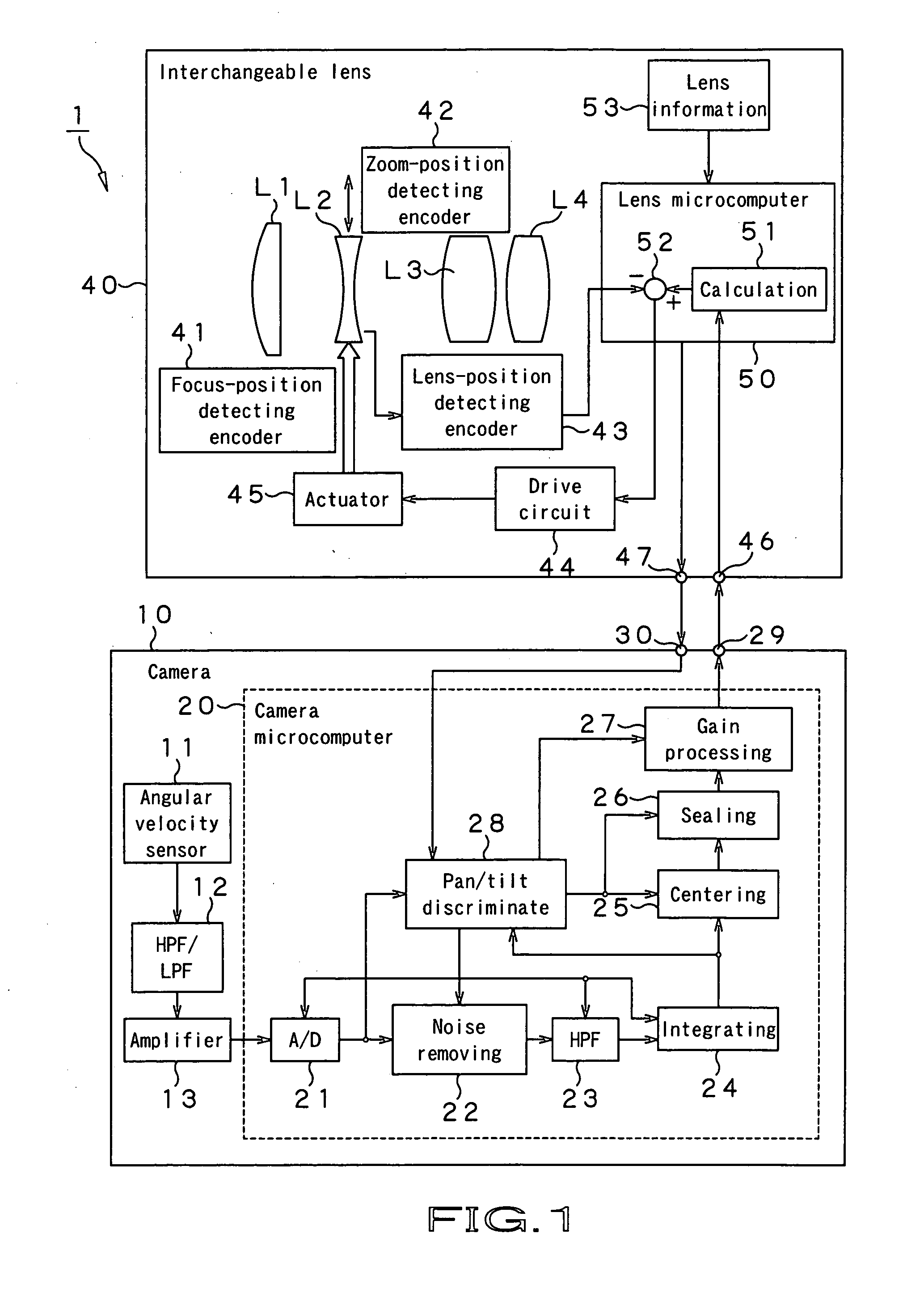
[0045] First, the camera system according to the present invention will be described with reference to FIG. 1. The camera system is generally indicated with a reference numeral 1.

[0046] As shown in FIG. 1, the camera system 1 according to the present invention includes a camera 10 as the body of the camera system 1, and an interchangeable lens 40 which is to be installed to the camera 10. The camera system 1 has installed therein a shake correcting function to correct a shake given to the camera system 1, for example, a camera shake caused by a tremble of the camera user's hand holding the camera system 1.

[0047] First, the camera 10 will be explained below. The camera 10 includes an angular velocity sensor 11, HPF / LPF (high-pass filter / low-pass filter) 12, amplifier 13 and a microcomputer 20 (will be referred to as “camera microcomputer” hereunder).

[0048] The angular velocity sensor 11 is a vibration gyro sensor to detect a shake of the camera 10 in two directions perpendicular to...

second embodiment

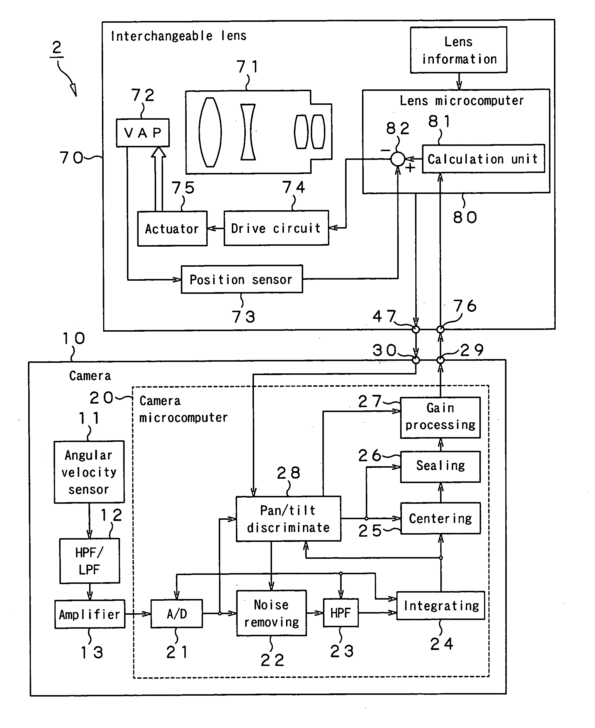
[0100] Next, the camera system according to the present invention will be described with reference to FIG. 5. The camera system is generally indicated with a reference numeral 2.

[0101] As shown in FIG. 5, this camera system 2 includes a camera 10 as a camera body, and an interchangeable lens 70 to be installed to the camera body. The camera system 2 has installed therein a shake correcting function to correct a shake given to the camera system 2 similarly to the camera system 1, for example, a camera shake caused by a tremble of the camera user's hand holding the camera during shooting.

[0102] Note that the camera 10 in the camera system 2 is exactly the same in construction as that having been described with reference to FIG. 1 and so elements of the camera 10 will be indicated with the same reference numerals as those in FIG. 1 and will not be explained in detail. When a shake is detected by an angular velocity sensor 11 in the camera 10, optical-correction angle information is ge...

third embodiment

[0114] Next, the camera system according to the present invention will be described with reference to FIG. 8. The camera system is generally indicated with a reference numeral 3.

[0115] As shown in FIG. 8, this camera system 3 includes a camera 10 as the camera body, and an interchangeable lens 110 to be installed to the camera body. The camera system 3 has installed therein a shake correcting function to correct a shake given to the camera system 3 similarly to the camera systems 1 and 2, for example, a camera shake caused by a tremble of the camera user's hand holding the camera during shooting.

[0116] First, the correcting optical system of the interchangeable lens 110 will be explained. The correcting optical system of the interchangeable lens 110 adopts a VAP which is different from the liquid-filled VAP used in the interchangeable lens 70 shown in FIG. 5.

[0117] The VAP used in the interchangeable lens 110 will be described. Since in the liquid-filled VAP used in the interchang...


PUM


Abstract

A camera system (1) is provided which includes an interchangeable lens (40) including a group of lenses (L1, L2, L3, L4) for imaging an object, and a camera (10) to which the interchangeable lens (40) is to be installed. The camera (10) includes a correction angle information calculating means (20) for calculating correction angle information as to the posture of the camera (10), and a first sending means (29) for sending calculated correction angle information to the interchangeable lens (40). The interchangeable lens (40) includes the lens (L2) which optically corrects angular shift on the basis of the correction angle information sent by the first sending means (29).

Description

TECHNICAL FIELD [0001] The present invention generally relates to a camera system uses a lens freely interchangeable by the camera user as necessary, and more particularly to a camera system in which a shake of a lens-interchangeable camera can be corrected during shooting, camera and an interchangeable lens. [0002] This application claims the priority of the Japanese Patent Application No. 2003-092348 filed on Mar. 28, 2003, the entirety of which is incorporated by reference herein. BACKGROUND ART [0003] Some of the conventional video cameras and still cameras have installed therein a camera-shake correcting function to correct a camera shake caused by a tremble of the camera user's hand holding the camera during shooting. Normally, the camera shake is corrected by image processing with the use of a CCD (charge-coupled device) imaging device or by optically correcting the optical axis displaced due to the camera shake. [0004] It is proposed in the Japanese Patent Application No. 14...

Claims


Application Information

Patent Timeline
Patent Type & Authority Applications(United States)
IPC IPC(8): G03B17/00G03B17/14G03B5/00G03B17/56
CPCG03B5/00G03B2217/005G03B2205/0015G02B27/648
Inventor MOMOCHI, NOBUCHIKAKAMEYAMA, TAKASHISUZUKI, KOJITERADA, HIROTSUGU
Owner SONY CORP
Why Eureka
Try Eureka