High density midplane

a high-density midplane and high-density technology, applied in the direction of printed circuit aspects, orthogonal pcbs mounting, electrical apparatus construction details, etc., can solve the problem that the system is not well suited for cross-connecting differential signals

Inactive Publication Date: 2006-04-06
AMPHENOL CORP
View PDF14 Cites 137 Cited by
  • Summary
  • Abstract
  • Description
  • Claims
  • Application Information

AI Technical Summary

Problems solved by technology

However, such systems are not well suited for cross-connecting differential signals because the pairs of conductors that form one differential signal cannot be adjacent in connectors on both sides of the midplane

Method used


Image

  • High density midplane
  • High density midplane
  • High density midplane

Examples


Embodiment Construction

[0026] This invention is not limited in its application to the details of construction and the arrangement of components set forth in the following description or illustrated in the drawings. The invention is capable of other embodiments and of being practiced or of being carried out in various ways. Also, the phraseology and terminology used herein is for the purpose of description and should not be regarded as limiting. The use of “including,”“comprising,” or “having,”“containing,”“involving,” and variations thereof herein, is meant to encompass the items listed thereafter and equivalents thereof as well as additional items.

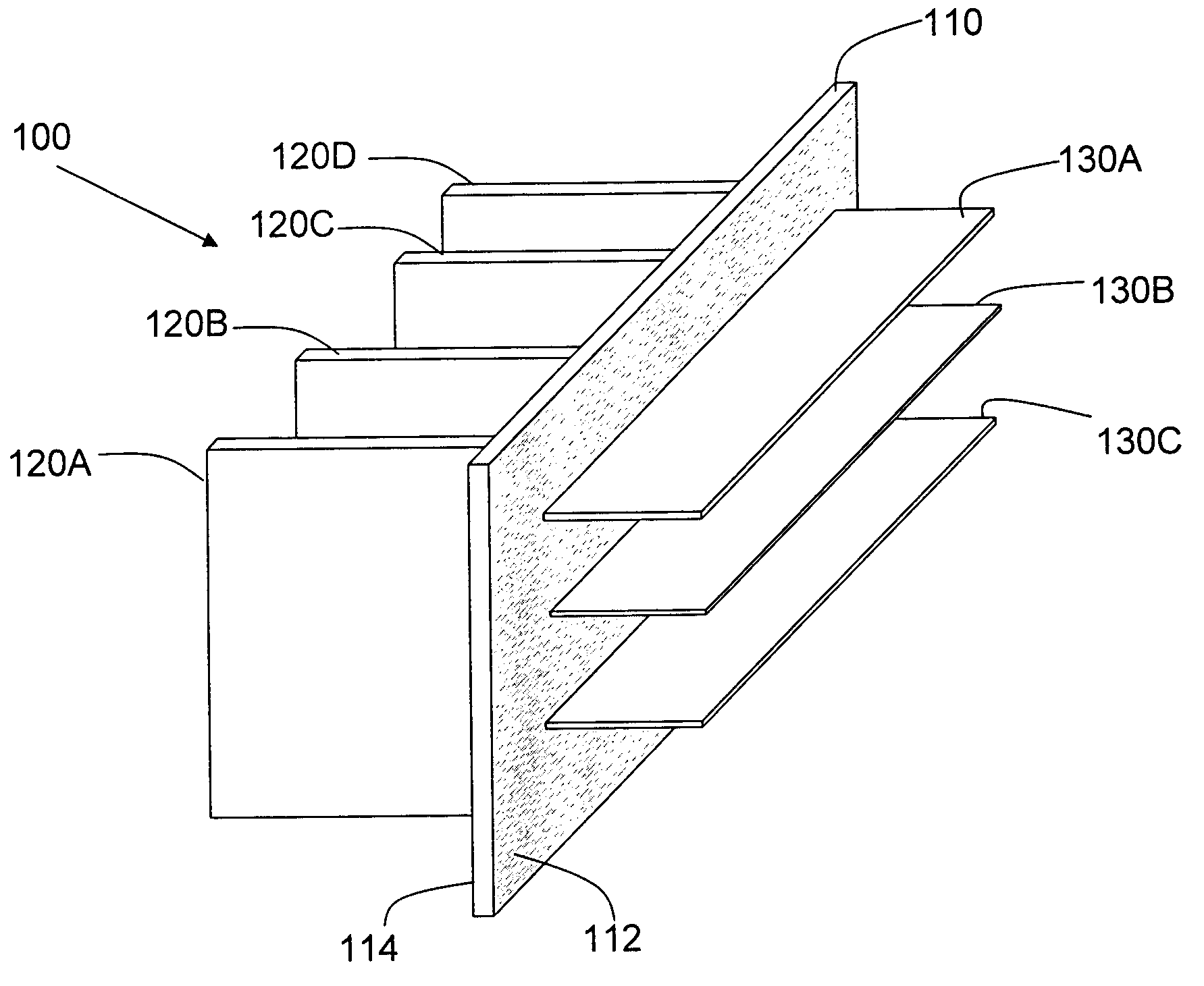
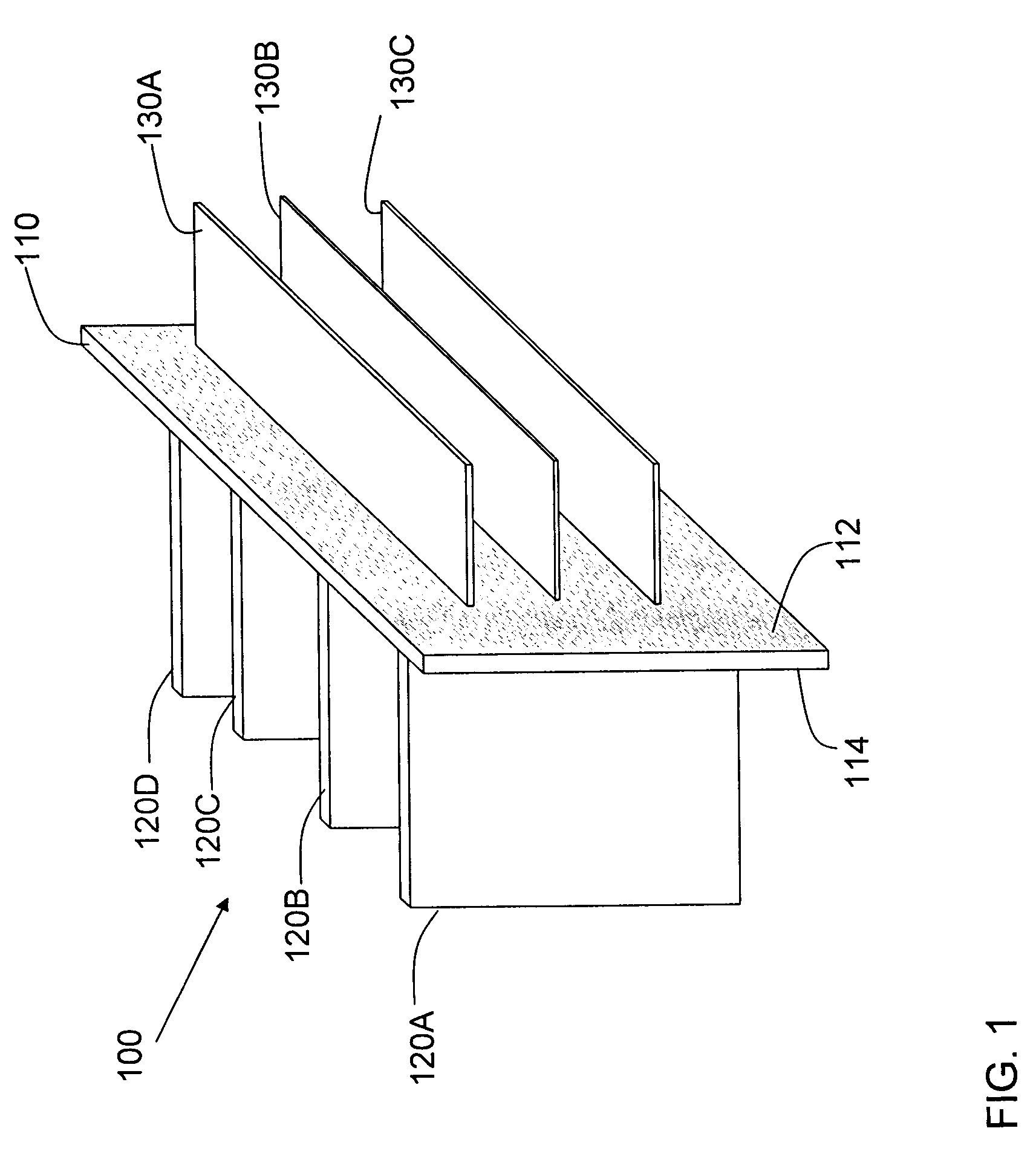
[0027]FIG. 1 is a sketch of an electronic system 100. Electronic system 100 is assembled with a midplane 110. Midplane 110 has a back 112 and a front 114.

[0028] Daughter cards 120A, 120B, 120C and 120D are inserted in midplane 110 from front side 114. Daughter cards 130A, 130B, 130C are inserted in midplane 110 from the back.

[0029] As in a conventional syste...


PUM


Abstract

An electronic system with multiple printed circuit boards interconnected through a midplane. Connectors are mounted on two sides of the midplane to facilitate connection of daughter cards from both the front and the back of the midplane. For cross-connecting coupling signals between daughter cards mounted to the front and daughter cards mounted to the back of the midplane, connectors mounted to the front and the back of the midplane are overlapped in certain regions. Within these regions, an efficient routing pattern is employed to cross-connect signals from the front of the midplane to the back of the midplane. The routing is achieved in a very small space but provides the desired impedance of the interconnects.

Description

BACKGROUND OF INVENTION [0001] 1. Field of Invention [0002] This invention relates generally to electronic systems and more particularly to the interconnection of circuit boards in electronic systems. [0003] 2. Discussion of Related Art [0004] Electronic systems are often assembled from multiple printed circuit boards. Each circuit board, which is sometimes called a “daughter card,” contains electronic components. The daughter card includes one or more electrical connectors that allow the circuits on the daughter card to be connected to other circuits in the system. [0005] Often, electrical signals are routed from one daughter card to another through a backplane. A backplane is a printed circuit board with many conducting paths, called “traces” or “tracks.” Connectors are mounted on the backplane to make connection to the traces. When the connectors on the daughter cards are mated with the connectors on the backplane, signal paths are established between the daughter cards. [0006] T...

Claims


Application Information

Patent Timeline
Patent Type & Authority Applications(United States)
IPC IPC(8): H05K1/00
CPCH05K1/14H05K7/1445H05K2201/044H05K2201/10189
Inventor REID, BRIAN P.
Owner AMPHENOL CORP
Why Eureka
Try Eureka