Bus deadlock avoidance

a technology for bus stops and deadlocks, applied in the direction of instruments, electric digital data processing, etc., can solve problems such as deadlock situations

Active Publication Date: 2006-04-06
ARM LTD
View PDF14 Cites 63 Cited by
  • Summary
  • Abstract
  • Description
  • Claims
  • Application Information

AI Technical Summary

Benefits of technology

[0013] Hence, any address transfers which could result in the interconnect logic being configured such that a deadlock situation can occur are prevented from being provided. However, any address transfers which could not result in a deadlock situation occurring can be propagated. Accordingly, it will be appreciated that this arrangement enables the configuration of the interconnect logic to be carefully controlled such that it cannot be arranged to enable a deadlock situation to occur.
[0044] By simply retaining a record associating each manipulated address transfer with its original identification signal, that original identification signal can readily be reinserted and propagated when the associated data transfer is being performed.

Problems solved by technology

Accordingly, because the slave logic unit does not receive that address transfer the interconnect logic cannot be configured by that address transfer into an arrangement which may result in a deadlock situation occurring.

Method used


Image

  • Bus deadlock avoidance
  • Bus deadlock avoidance
  • Bus deadlock avoidance

Examples


first embodiment

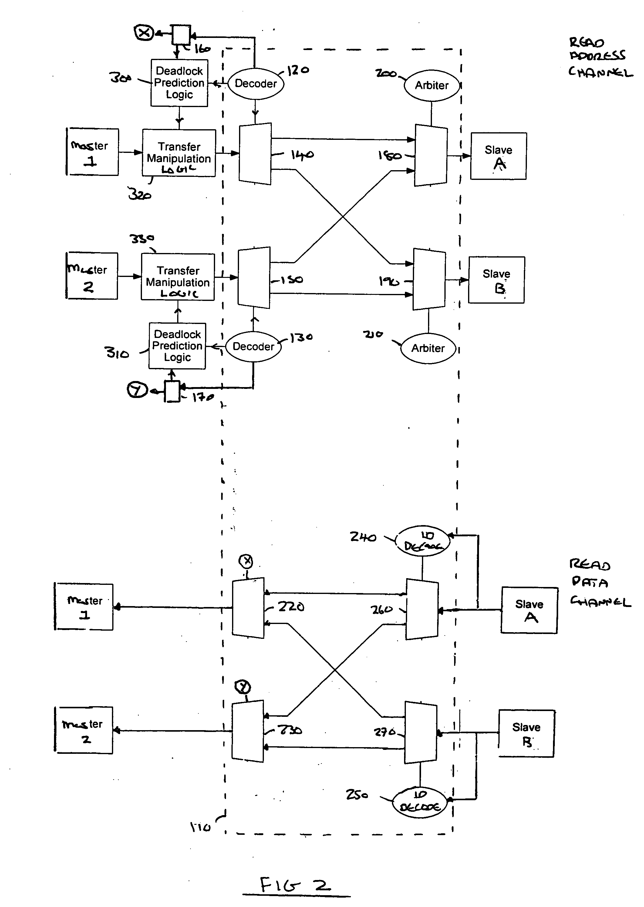
[0056]FIG. 2 illustrates a data processing system in which deadlock prediction logic 300; 310 are provided which signal respective transfer manipulation logic 320; 330 to prevent the transmission of address transfers to a bus interconnect 110 when it is determined that a deadlock situation could occur.

[0057] Each master logic unit and slave logic unit is arranged to communicate using an Advanced extensible Interface (AXI). The Advanced extensible interface provides a number of channels over which information and data can be provided. These channels comprise a read address channel, a write address channel, a write data channel, a read data channel, and a write response channel.

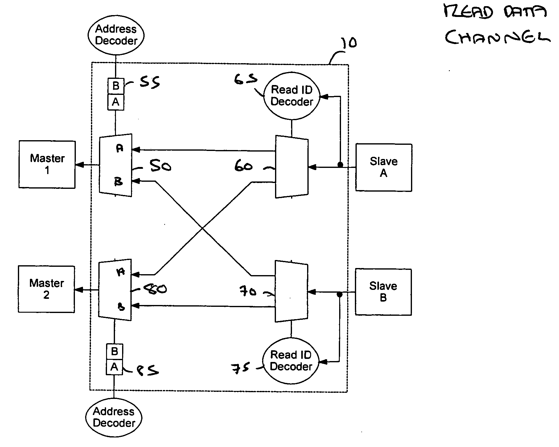
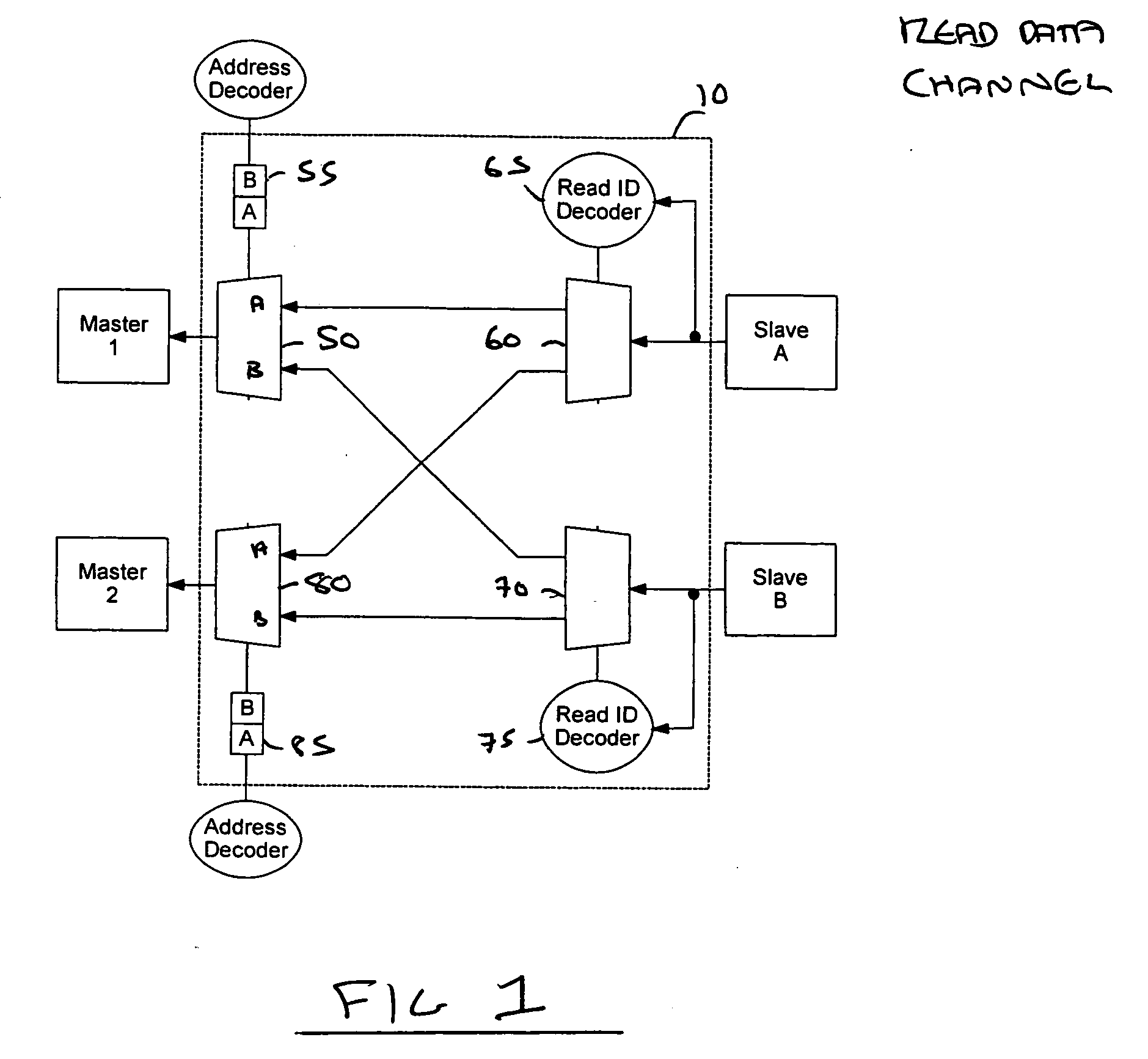
[0058]FIG. 2 illustrates elements of the data processing system associated with the read address channel (upper half of FIG. 2) and the read data channel (lower half of FIG. 2). The other channels have been omitted to improve clarity of the drawings. Each channel comprises a number of signal paths and buses. ...

second embodiment

[0069]FIG. 3 illustrates a data processing system in which transfer manipulation logic 340; 350 is provided which prevents the transmission of address transfers from the bus interconnect 110 to slave logic units in the form provided by master logic units. Instead, a manipulated address transfer is propagated from the transfer manipulation logic 340; 350 which, as will be discussed in more detail below, ensures that a deadlock situation can not occur.

[0070] The initial stages of any address transfer and the configuration of the bus interconnect 110 may be the same as that described with respect to FIG. 2 for transfers which are allowed to proceed. However, transfer manipulation logic 340; 350 is provided between the bus interconnect 110 and a respective slave logic unit. The transfer manipulation logic 340; 350 is arranged to manipulate signals provided by the bus interconnect 110 and to transmit a manipulated address transfer to its associated slave.

[0071] Each slave logic unit is...

third embodiment

[0074]FIG. 4 illustrates a data processing system in which deadlock prediction logic 400; 410 is provided which prevents the transmission of address transfers from the bus interconnect 110 to slave logic units by providing signals to an associated arbiter 200; 210 when it is determined that a deadlock situation could occur.

[0075] The initial stages of any address transfer and the configuration of the bus interconnect 110 may be the same as that described with respect to FIG. 2 for transfers which are allowed to proceed.

[0076] Deadlock prediction logic 400; 410 is provided which receives details of address transfers and determines whether a condition is met which may result in a deadlock situation occurring. If the deadlock prediction logic 400; 410 determines that a deadlock situation will occur then a signal is provided to the associated arbiter 200; 210 which causes the transmission of that address transfer from the bus interconnect 110 to be prevented by preventing the arbiter ...


PUM


Abstract

Bus logic, a data processing apparatus and a method is disclosed. The bus logic is operable to couple a plurality of master logic units with a plurality of slave logic units to enable data transfers to occur, each master logic unit being operable to perform an address transfer which, when received by a specified one of the plurality of slave logic units, causes an associated data transfer to be performed between that master logic unit and the specified one of the plurality of slave logic units, each of the plurality of slave logic units being required to complete a data transfer, once initiated, prior to performing any further data transfers, at least one of the plurality of slave logic units being operable to perform data transfers in an order which differs from that in which associated address transfers were received by that slave logic unit. The bus logic comprises interconnect logic configurable, responsive to an address transfer, to couple a master logic unit with a slave logic unit to enable a data transfer to take place. The bus logic also comprises deadlock prediction logic operable to receive information indicative of each address transfer and to determine whether propagation of that address transfer may cause the interconnect logic to be configured such that a deadlock situation can occur in which data transfers are unable to can take place between affected master logic units and slave logic units and, if so, to prevent the propagation of that address transfer. This enables the configuration of the interconnect logic to be carefully controlled such that it cannot be arranged to enable a deadlock situation to occur.

Description

BACKGROUND OF THE INVENTION [0001] 1. Field of the Invention [0002] The present invention relates to techniques for avoiding bus deadlock and, in particular, to bus logic, an apparatus and a method for preventing bus deadlock situations occurring. [0003] 2. Description of the Prior Art [0004] The problem of bus deadlock is known. A bus deadlock will typically occur when the configuration of the bus prevents logic units coupled thereto from performing or completing data transfers. When the deadlock occurs it is often very difficult to restore the bus to a normal operating state. Therefore, when deadlock occurs it is generally required that the configuration of the bus is reset, which will also typically impact on the configuration and operation of logic units coupled thereto. Hence, these logic units may also need to be reset to enable the required data transfers to be performed or completed. Accordingly, it will be appreciated that bus deadlock can have a devastating impact on the p...

Claims


Application Information

Patent Timeline
Patent Type & Authority Applications(United States)
IPC IPC(8): G06F13/00
CPCG06F13/364
Inventor HARRIS, ANTHONY J.MATHEWSON, BRUCE J.WRIGLEY, CHRISTOPHER E.
Owner ARM LTD
Why Eureka
Try Eureka