Variable valve train mechanism of internal combustion engine

a technology of variable valve train and internal combustion engine, which is applied in the direction of valve details, valve arrangements, valve drives, etc., can solve the problems of increasing the reliability of operation of the variable valve train mechanism, increasing the manufacturing time and cost, and difficulty in controlling the relative phase angle between the input portion and the output portion

Inactive Publication Date: 2006-04-13
YAMAHA MOTOR CO LTD
View PDF4 Cites 22 Cited by
  • Summary
  • Abstract
  • Description
  • Claims
  • Application Information

AI Technical Summary

Problems solved by technology

In the type of variable valve train mechanism in which a relative phase angle between the input portion and the output portion of the intermediate driving mechanism is changed by means of the helical spline mechanism as intermediate phase angle changing means so that a lift and the like of the valve is controlled, the helical spline mechanism can swing the input portion and the output portion relative to each other, but has difficulty in controlling a relative phase angle between the input portion and the output portion to a specified angle.
Therefore, in some cases, precise control of a valve lift and the opening and closing timing of the valve is difficult to achieve, which results in a problem of difficulty in increasing reliability of operation of the variable valve train mechanism.
Further, manufacturing the helical spline mechanism is difficult, resulting in elevated manufacturing time and cost.
Further, since adjusting valve lift is accomplished by controlling a relative phase angle between the input portion and the output portion, the timing of a maximum lift cannot be changed in some devices.

Method used


Image

  • Variable valve train mechanism of internal combustion engine
  • Variable valve train mechanism of internal combustion engine
  • Variable valve train mechanism of internal combustion engine

Examples


Embodiment Construction

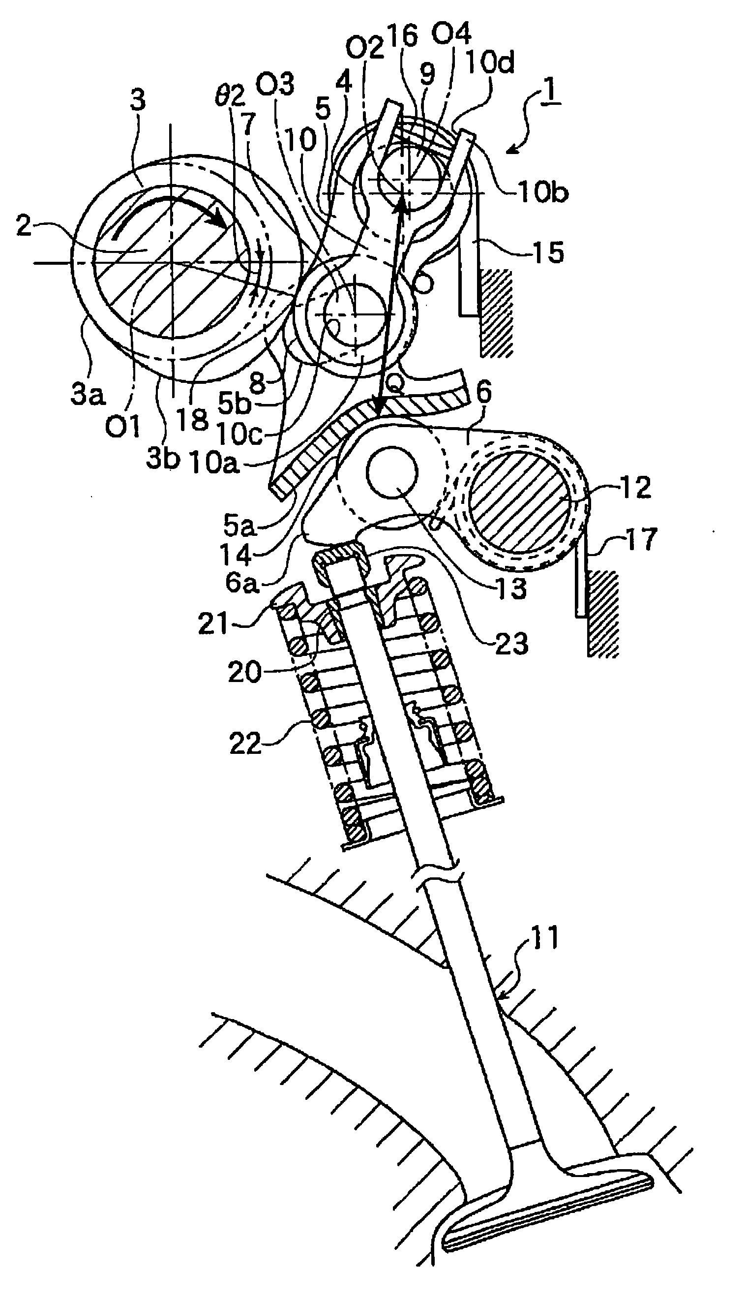
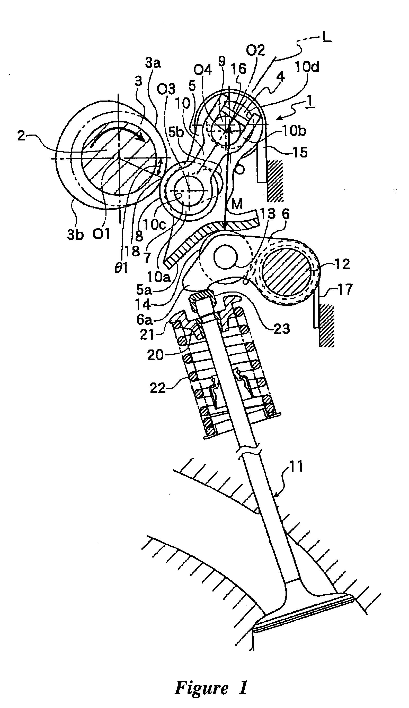
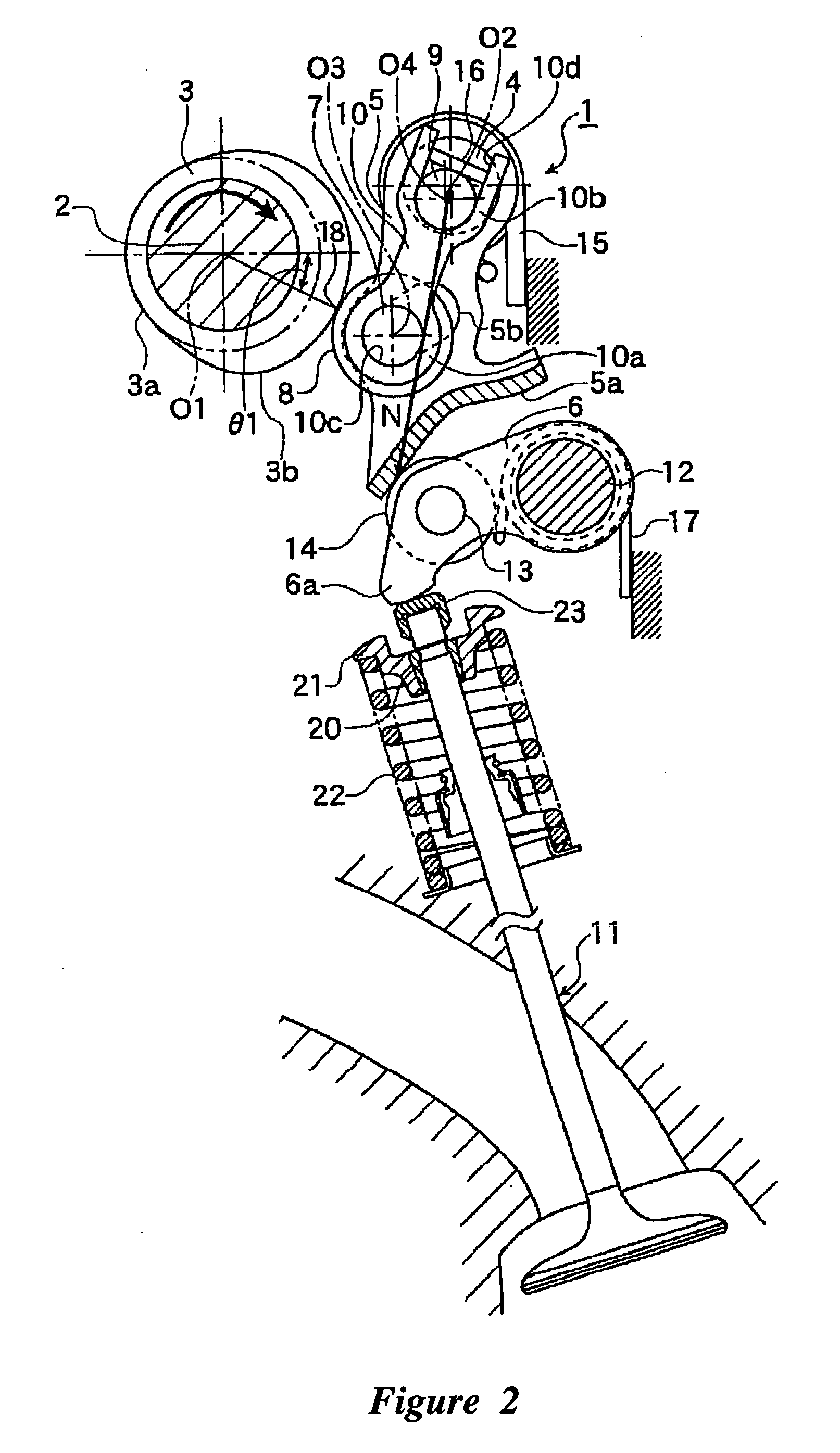
[0040] Reference numeral 1 in FIG. 1 denotes a variable valve train mechanism for an intake valve 11 for one of the cylinders of a multi-cylinder gasoline engine. The variable valve train mechanism is disclosed in the context of an internal combustion engine because it has particular utility in this context. Such internal combustion engines can be used in any context and be incorporated into any type of device, such as, for example, but without limitation, vehicles including at least automobiles, motorcycles, golf carts, heavy-duty transportation, boats, watercraft, outboard motors, and industrial applications including at least generators and pumps and the like. However, the variable valve train mechanism can be used in other contexts, such as, for example, but without limitation, any type of fluid control valves, for liquids, gases, or solids.

[0041] The variable valve train mechanism 1 can have a camshaft 2, a rotational cam 3, a swing shaft 4, a swing cam 5, and a rocker arm 6, ...


PUM


Abstract

A rotational cam can be disposed on a camshaft rotationally driven by a crankshaft of an internal combustion engine. A swing cam can be swingable through the rotational cam. The swing cam has a rotational cam abutment portion which contacts the rotational cam and transmits driving force from the rotational cam to the swing cam. An abutment portion displacing mechanism can be provided for displacing the rotational cam abutment portion to change a relative distance between the rotational cam abutment portion and a center axis of the swing shaft. Changing the relative distance allows changing a lift and the like of a valve.

Description

RELATED APPLICATIONS [0001] This continuation application is a national phase filing under 35 U.S.C. § 371 of PCT Application No. PCT / JP2004 / 003076, filed Mar. 10, 2004, which claims priority to Japanese Application Nos. 2003-065400, filed Mar. 11, 2003, and 2003-208302, filed Aug. 21, 2003, the entire contents of all of which are hereby incorporated by reference.BACKGROUND OF THE INVENTIONS [0002] 1. Field of the Inventions [0003] The present inventions relate to a variable valve train mechanism of an internal combustion engine capable of changing a lift and the like of an intake valve or an exhaust valve of the internal combustion engine. [0004] 2. Description of the Related Art [0005] Variable valve train mechanisms have recently been more widely incorporated into mass produced engines. Some variable vale train mechanisms are designed to control lift, and the like, of an intake valve or an exhaust valve of an internal combustion engine according to operating conditions of the int...

Claims


Application Information

Patent Timeline
Patent Type & Authority Applications(United States)
IPC IPC(8): F01L1/34F01L1/08F01L13/00
CPCF01L1/08F01L13/0063F01L2013/0068F01L2105/00F01L2305/00
Inventor FUJITA, HIDEOHATAMURA, KOICHI
Owner YAMAHA MOTOR CO LTD
Why Eureka
Try Eureka