
Articulating linkage exercise machine

Active Publication Date: 2006-04-13
CORE HEALTH & FITNESS
View PDF37 Cites 38 Cited by
  • Summary
  • Abstract
  • Description
  • Claims
  • Application Information

AI Technical Summary

Benefits of technology

[0007] Accordingly, an elliptical exercise machine has been developed that can reduce the overall footprint of the machine. In accordance with one embodiment of the machine, a linkage assembly that constrains a pair of foot pedals for elliptical movement is positioned entirely ahead of a rearmost portion of the foot pedals. In other words, the foot pedals or foot supports are cantilevered to a location rearward of the linkage assembly.

Problems solved by technology

While the elliptical motion generated by these machines has been desired by many fitness enthusiasts, the elongated foot supports have dictated relatively large machine foot prints.
Thus, each elliptical machine required a large amount of floor space within a commercial gym setting or within a home gym.

Method used


Image

  • Articulating linkage exercise machine
  • Articulating linkage exercise machine
  • Articulating linkage exercise machine

Examples


Embodiment Construction

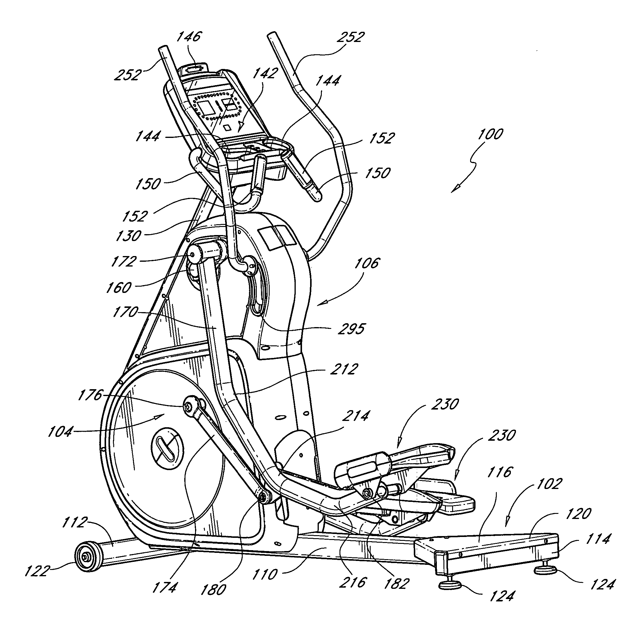
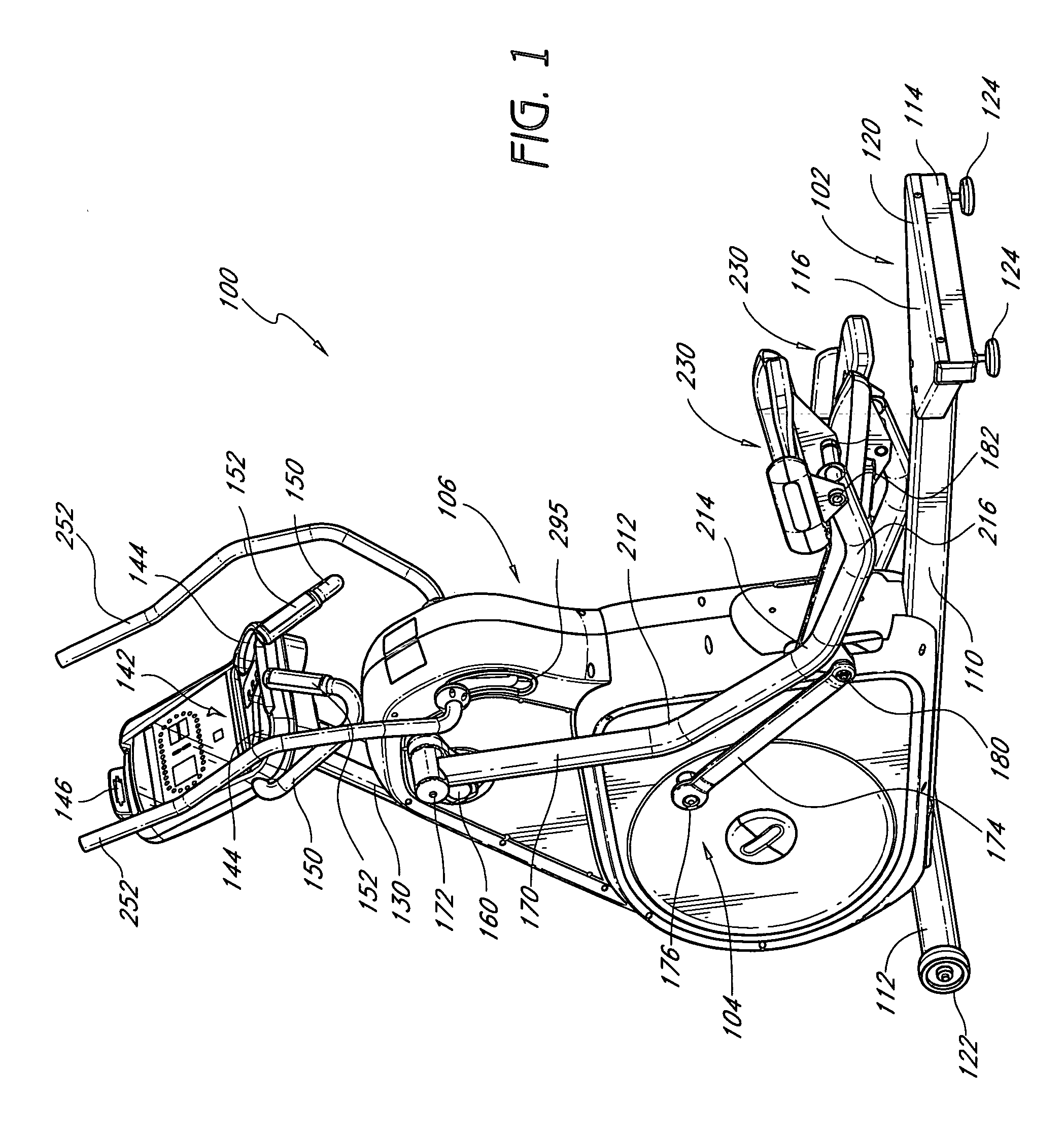
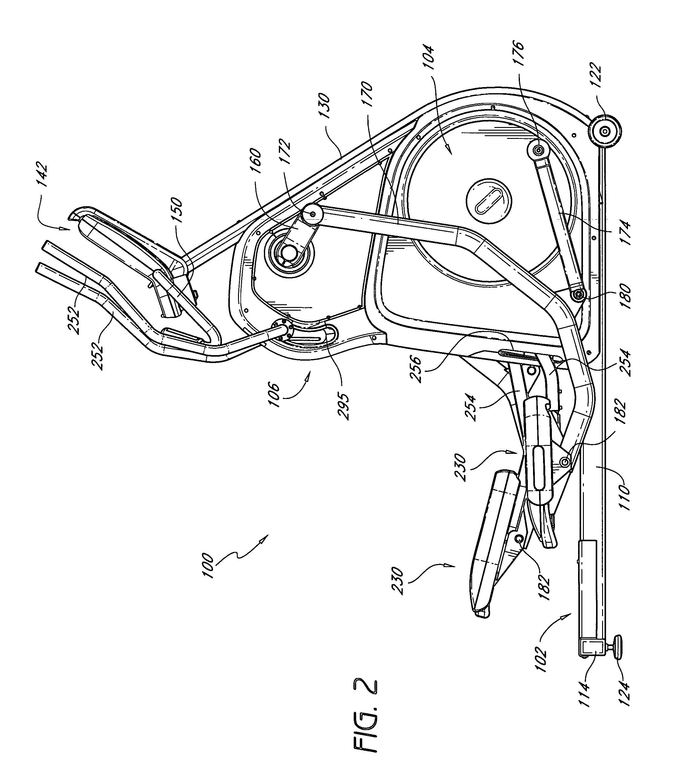
[0027] With reference initially to FIGS. 1-7, the illustrated exercise machine 100 is adapted for stationary positioning on a floor during exercise. As such, the machine 100 comprises a frame assembly 102 that supports an operating linkage 104 (see FIG. 8 for a view of a majority of the frame assembly, FIG. 9 for a skeletal illustration of the operating linkage 104 and FIG. 10 for a clearer view of the integration of the frame 102 and the linkage 104). A housing 106 encloses a substantial portion of both the frame 102 and the linkage 104.

[0028] With reference now to FIG. 1, the frame 102 preferably comprises a longitudinally extending center beam 110. At the forward end of the center beam 110, a laterally extending front cross beam 112 is secured to the center beam 110. At the rearward end of the center beam 110, a rear cross beam 114 is secured to the center beam 110. Together, the center beam 110, the front cross beam 112 and the rear cross beam 114 define a support base. Other s...


PUM


Abstract

An elliptical machine has a frame and an operating linkage between the frame and foot supports. Each side of the operating linkage comprises five links that are connected with five pin joints. A foot support is connected to each side of the operating linkage with each of the five pin joints being positioned forward of the foot support.

Description

RELATED APPLICATIONS [0001] This application claims the priority benefit of U.S. Provisional Patent Application No. 60 / 592,615, filed Jul. 30, 2004, which is hereby incorporated by reference in its entirety.BACKGROUND OF THE INVENTION [0002] 1. Field of the Invention [0003] The present invention generally relates to elliptical exercise machines. More particularly, the present invention relates to elliptical exercise machines featuring articulating linkages that generate elliptical foot traces for a user. [0004] 2. Description of the Related Art [0005] Most previous elliptical exercise machines have employed guides or tracks that forced one end of a foot support to move in a substantially linear manner while the other end of the foot support rotated about a crank axis. A user's foot would be positioned at an intermediate location along the foot support. As a result of this construction, the movement of the user's foot would generate a generally elliptical trace. [0006] While the elli...

Claims


Application Information

Patent Timeline
IPC IPC(8): A63B22/04A63B22/06
CPCA63B21/005A63B21/0058A63B22/0007A63B22/001A63B22/0015A63B22/0664A63B71/0619A63B2022/0682A63B2071/025A63B2220/76A63B2225/30A63B2225/682A63B2225/687A63B2230/06A63B2230/062
Inventor CORNEJO, VICTOR TORRESCHILES, MARK WILLIAMDEY, JAMESMARIN, FELIPE J.CORBALIS, KEVIN PATRICK
Owner CORE HEALTH & FITNESS
Learn More