
Retractable protective dome for space vehicle equipment

a technology for space vehicles and protective domes, which is applied in the direction of extensible doors/windows, door/window protection devices, and cosmonautic thermal protection, etc., which can solve problems such as interference with openings

Inactive Publication Date: 2006-04-20
THE BOEING CO
View PDF51 Cites 19 Cited by
  • Summary
  • Abstract
  • Description
  • Claims
  • Application Information

AI Technical Summary

Benefits of technology

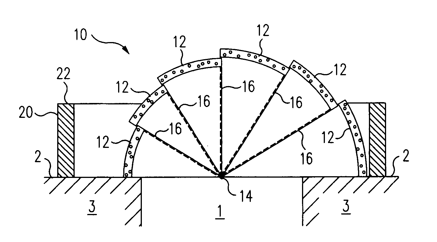
[0006] In accordance an exemplary embodiment of the present invention, a simple, reliable, telescopically retractable dome is provided that can be deployed over a docking mechanism, hatch, or other equipment disposed on the surface of a space vehicle to provide at least thermal and MMOD protection for the equipment, and that is capable of being retracted substantially out of the way of the protected equipment when not in use, to avoid interference with access to and use of the equipment.

Problems solved by technology

The environment of space is harsh and can subject the equipment used on the exterior of space vehicles, space stations, and space exploration habitats, such as hatches, docking mechanisms, antennae, cameras, sensors and the like, to a wide variety of potentially harmful agents, including strong thermal radiation and micrometeoroid impacts.
Conventional space vehicle protective doors and shields are typically generally planar in shape and cantilevered to one side of the area of the affected equipment when disposed in an open position, and can therefore interfere with the openings that they close, or the equipment on the surface of the vehicle that they are intended to protect, such as a docking ring or an antenna.
Consequently, a long-felt but as yet unsatisfied need exists for a simple, reliable protective shield, or cover, that can be deployed over a docking mechanism, hatch, or other equipment used on the surface of a space vehicle to provide at least thermal and MMOD protection for the equipment, and that overcomes the disadvantages of conventional doors and shields as discussed above.

Method used


Image

  • Retractable protective dome for space vehicle equipment
  • Retractable protective dome for space vehicle equipment
  • Retractable protective dome for space vehicle equipment

Examples


Embodiment Construction

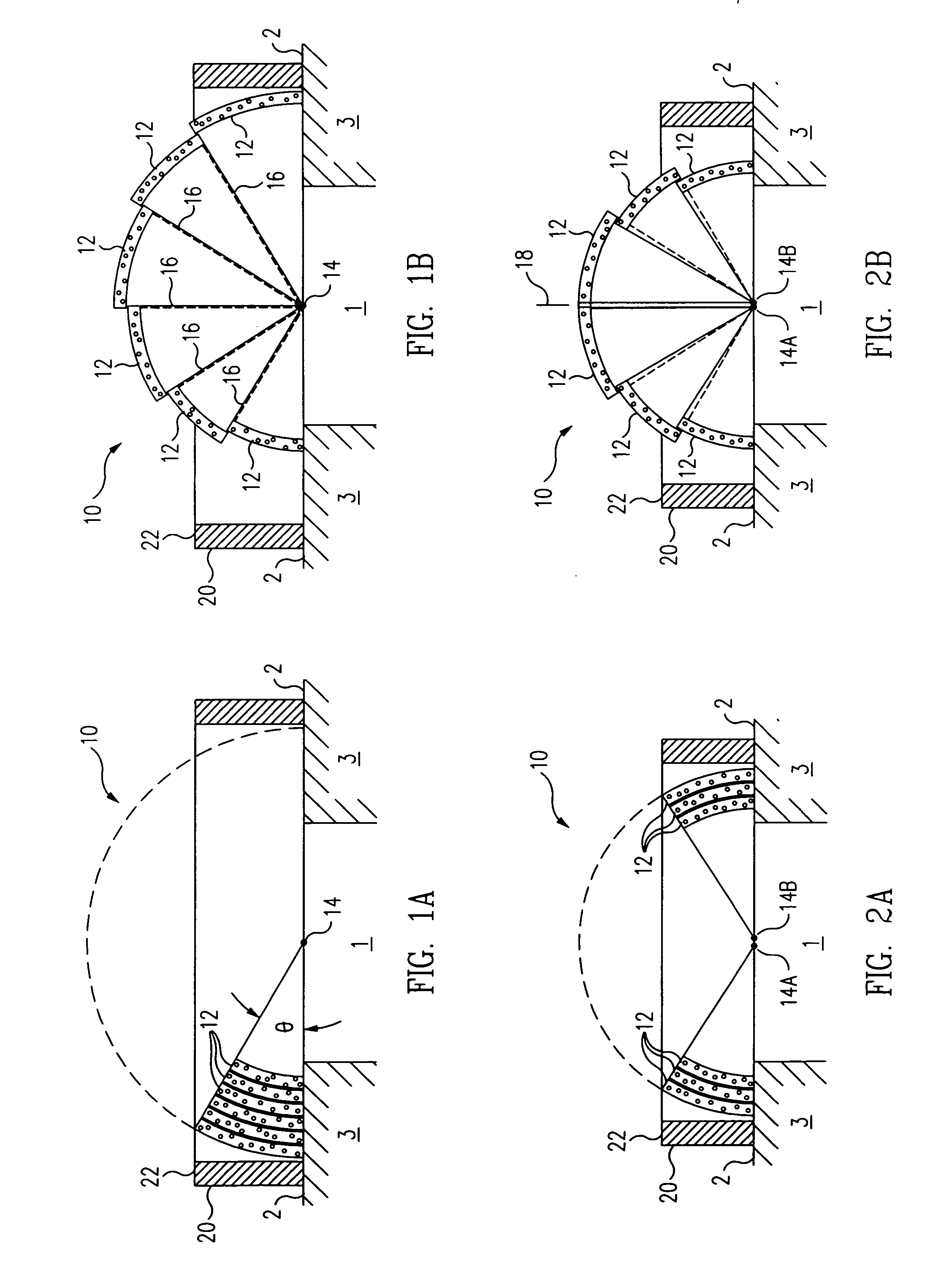
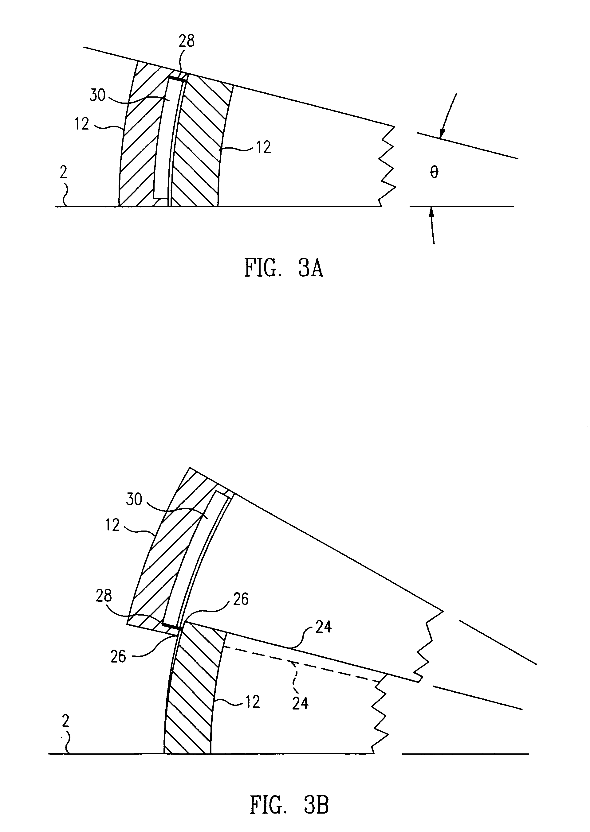
[0019] A first exemplary embodiment of a rigid, telescopically retractable protective dome 10 for protecting a feature 1 on an exterior surface 2 of a space vehicle 3 in accordance with the present invention is illustrated in FIGS. 1A and 1B in the retracted and deployed positions, respectively. As may be seen in FIG. 1A, in which the protective dome 10 is shown in the fully retracted position, the dome comprises a plurality of rigid, arcuate segments 12, each having opposite ends respectively pinioned at opposite sides of the feature 1 at about the surface 2 of the vehicle 3 for independent rotational movement of the segment about an axis of rotation 14 (seen end-on in the figures) extending through the two opposite ends thereof, and through an arcuate path of revolution extending over the feature, as indicated by the arcuate dashed line in FIG. 1A.

[0020] In the particular telescoping dome 10 embodiments illustrated in the figures, each of the arcuate segments 12 comprises a segme...


PUM


Abstract

A retractable rigid dome for protecting a feature, such as a docking mechanism, a hatch or other equipment on an exterior surface of a space vehicle, includes a plurality of rigid arcuate segments, each having opposite ends respectively pinioned at opposite sides of the feature at about the surface of the vehicle for rotational movement about an axis of rotation extending through the opposite ends thereof and through an arcuate path of rotation extending over the feature. The radial sizes of the segments are staggered such that, in a fully deployed position of the dome, in which adjacent segments are rotated apart from each other at a maximum relative angle therebetween, the segments combine to form an arcuate shield over the feature, and in a retracted position of the dome, in which adjacent segments are rotated together at a common angle relative to the surface of the vehicle, the segments are nested in radial alignment with each other.

Description

RELATED APPLICATIONS [0001] This application is related to U.S. application Ser. No. ______ [Attorney Docket No. M-15516 US], filed herewith, which is incorporated herein by reference in its entirety.SPONSORED RESEARCH OR DEVELOPMENT [0002] The invention described herein was made in the performance of work under NASA Contract No. NAS8-01099 and is subject to the provisions of Section 305 of the National Aeronautics and Space Act of 1958 (72 Stat.435: 42 U.S.C. 2457).STATEMENT REGARDING FEDERALLY TECHNICAL FIELD [0003] This invention relates to protective shields for space vehicles in general, and in particular, to telescopically retractable domes for providing thermal and micrometeoroid and orbital debris (“MMOD”) protection for docking mechanisms, hatches, and other equipment disposed on an exterior surface of a space vehicle, space station, space exploration habitat, and the like. BACKGROUND [0004] The environment of space is harsh and can subject the equipment used on the exterio...

Claims


Application Information

Patent Timeline
IPC IPC(8): E06B3/12
CPCB64G1/54B64G1/56B64G1/58E06B3/92
Inventor CLARK, PAUL R.MESSINGER, ROSS H.
Owner THE BOEING CO
Learn More