Wellbore signal generator

a signal generator and wellbore technology, applied in seismology, instruments, acoustic wave reradiation, etc., can solve the problems of impulsive sources limited by depth restrictions, realizing their potential in reverse vsp, damage to casings and cements, etc., to achieve the effect of minimizing the annular area

Active Publication Date: 2006-04-20
Z SEIS CORP
View PDF16 Cites 27 Cited by
  • Summary
  • Abstract
  • Description
  • Claims
  • Application Information

AI Technical Summary

Benefits of technology

[0014] The present invention may also be embodied as a method of generating a seismic signal in a formation by disposing a tool in a wellbore casing, wherein the tool comprises a plurality of electromagnets, supplying electrical power to the tool, and selectively applying the electrical power to the electromagnets so as to generate a displacement in the casing. The displacement in the casing may be a vibrating or rotating displacement. In certain embodiments, the tool is sized so as to minimize an annular area formed between the tool and the wellbore casing.

Problems solved by technology

Borehole seismic sources are used routinely in crosswell surveys but have not realized their potential in reverse VSP because they are generally low-powered, high-frequency, or unreliable.
Impulsive sources, such as bolt air guns, sparkers, and explosives, generate high power but can cause damage to casing and cement.
Impulsive sources also limited by depth restrictions.
The fluid-coupled sources are operationally simple and cause no borehole damage, but suffer from low output, particularly at low frequencies.
In addition, fluid-coupled sources must be operated in fluid filled wells, thus limiting their use in gas reservoirs.
Clamped sources provide improved performance at low frequencies but can cause casing damage and are generally more complicated and expensive to deploy and operate.

Method used


Image

  • Wellbore signal generator
  • Wellbore signal generator
  • Wellbore signal generator

Examples


Embodiment Construction

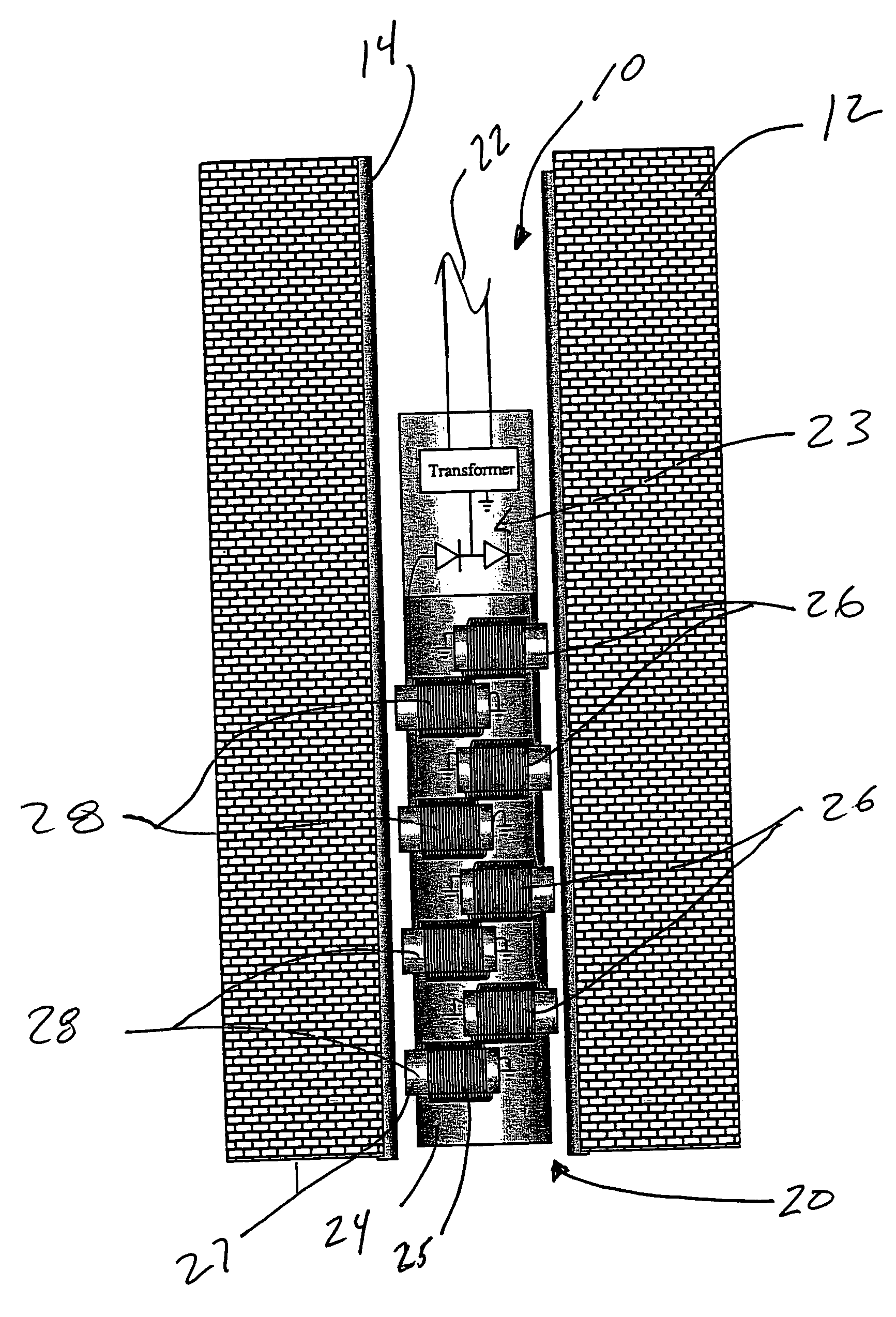
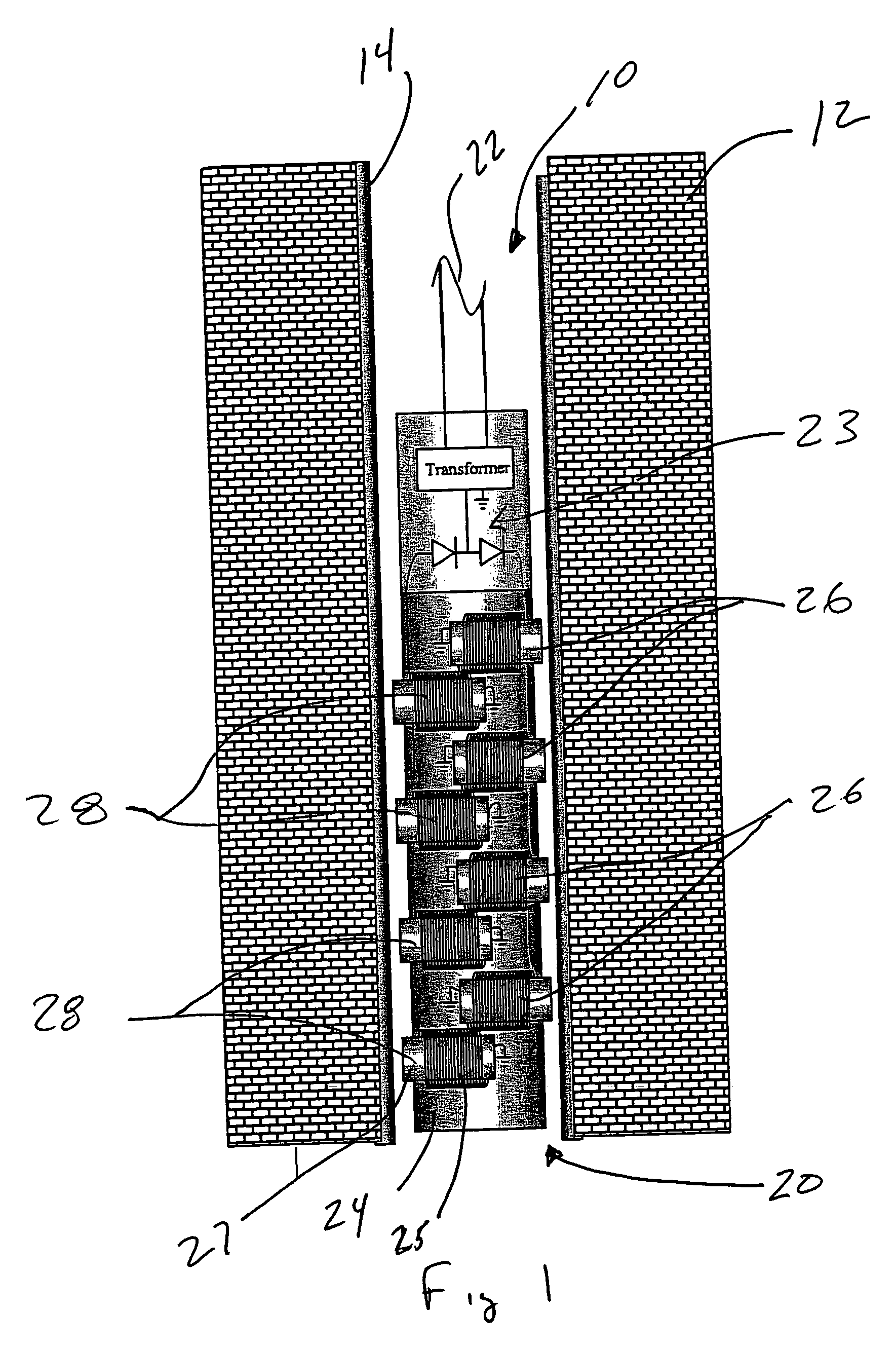
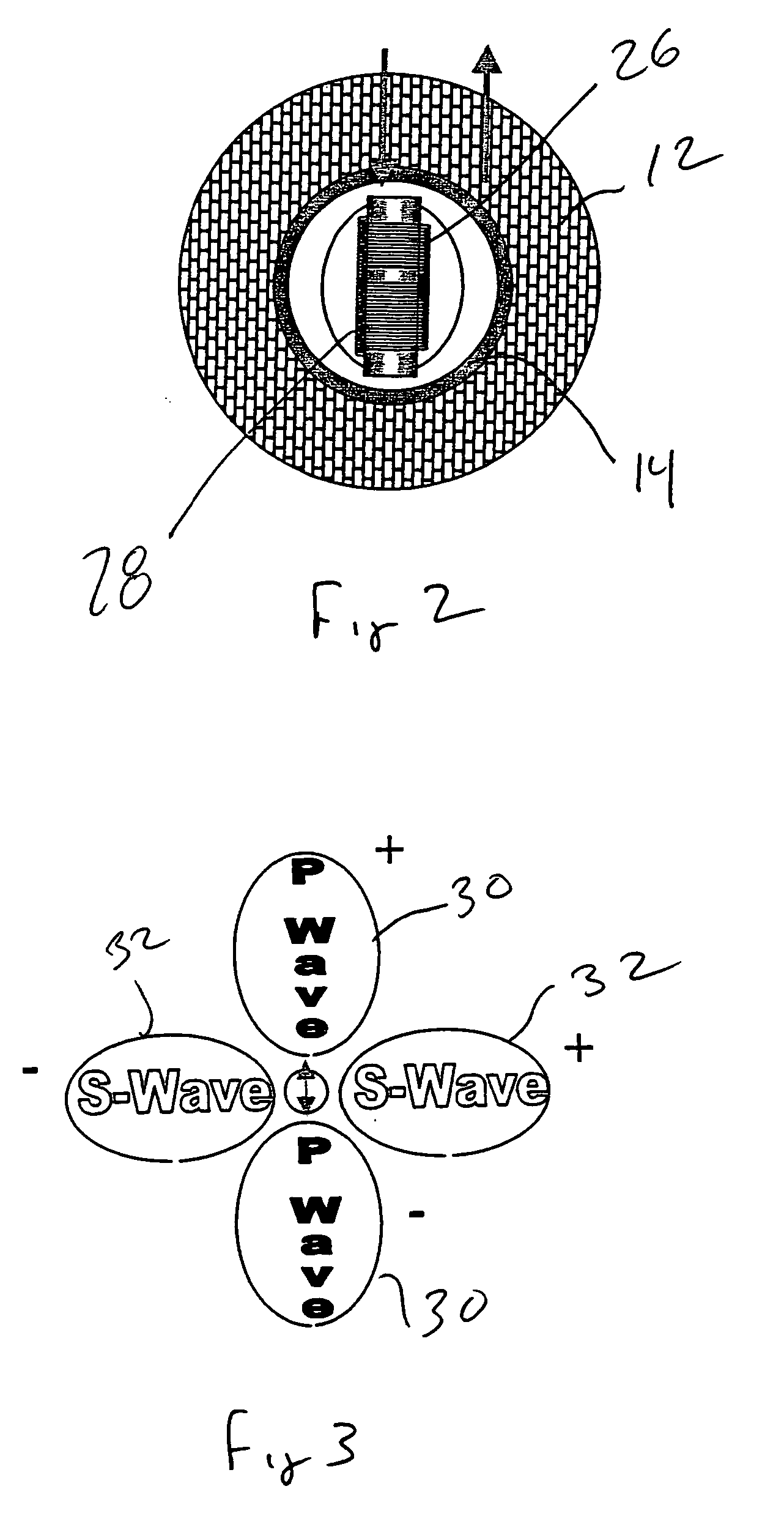
[0010] The embodiments of the present invention are directed toward methods and apparatus for generating a seismic signal with a signal generator comprising a tool body disposed in a casing. A first and second electromagnets are disposed within the tool body such that the second electromagnet is opposite the first electromagnet. A power supply selectively provides electrical current to the first and second electromagnets so as to displace the casing and generate a seismic signal in the surrounding formation.

[0011] In one embodiment, a signal generator comprises a tool body operable to be disposed in a casing. A first electromagnet is disposed within the tool body, which may be suspended on and powered through, a wireline. A second electromagnet is disposed within the tool body opposite the first electromagnet. A power supply is operable to selectively provide electrical current to the first and second electromagnets so as to displace the casing. In certain embodiments, the power su...


PUM


Abstract

Methods and apparatus for generating a signal with a signal generator comprising a tool body disposed in a tubular member. A first and second electromagnets are disposed within the tool body such that the second electromagnet is opposite the first electromagnet. A power supply selectively provides electrical current to the first and second electromagnets so as to displace the tubular member and generate a signal in the surrounding formation.

Description

CROSS-REFERENCE TO RELATED APPLICATIONS [0001] Not Applicable. STATEMENT REGARDING FEDERALLY SPONSORED RESEARCH OR DEVELOPMENT [0002] Not Applicable. BACKGROUND [0003] The present invention relates generally to methods and apparatus for seismic exploration systems and more particularly to borehole deployed seismic systems. Still more particularly, the present invention relates to methods and apparatus for generating seismic, acoustic, or other signals within a borehole. [0004] High-resolution seismic formation evaluation methods have been enabled by technology such as three-dimensional vertical seismic profiling (3-D VSP) and crosswell seismic tomography. These technologies can provide high-grade imaging data gathered from certain formations and fluids within a reservoir. This imaging data can be used by an operator to target areas within the formation most likely to produce hydrocarbons, thus resulting in improved production at reduced costs. [0005] Borehole seismic surveys have be...

Claims


Application Information

Patent Timeline
Patent Type & Authority Applications(United States)
IPC IPC(8): G01V1/00
CPCG01V1/04G01V1/52
Inventor MINTO, JAMES
Owner Z SEIS CORP
Why Eureka
Try Eureka