High contrast stereoscopic projection system

Active Publication Date: 2006-04-20
INTERDIGITAL CE PATENT HLDG
View PDF11 Cites 19 Cited by
  • Summary
  • Abstract
  • Description
  • Claims
  • Application Information

AI Technical Summary

Benefits of technology

[0010] The present invention provides a stereoscopic projection system that utilizes both of the oppositely polarized light signals, enhances the contrast ratio for video images, particularly in the dark state, and reduces contouring artifacts. The stereoscopic projection system, comprises two channels, each having two LCOS imagers that modulate light on a pixel-by pixel basis. A first polarizing beam splitter is configured to direct light of a first polarization onto the first channel first stage LCOS imager and direct light of a second polarization, opposite the first polarization, onto the second channel first stage LCOS imager. A relay lens system directs the output of the first stage imagers into a second polarizing beam splitter. The second polarizing beam splitter is configured to direct light of the second polarization onto the first channel second stage LCOS imager and direct light of the first polarization onto the second channel second stage LCOS imager. Since both polarizations of light are used throughout the stereoscopic projection system greater illumination efficiency may be achieved. Because each channel is modulated in two stages, greater contrast and addressing depth may be achieved.

Problems solved by technology

One of the major disadvantages of existing LCOS systems is the difficulty in reducing the amount of light in the dark state, and the resulting difficulty in providing outstanding contrast ratios.
This is, in part, due to the leakage of light, inherent in LCOS systems.
This can lead to contouring artifacts.
This improves some pictures, but does little for pictures that contain high and low light levels.

Method used


Image

  • High contrast stereoscopic projection system
  • High contrast stereoscopic projection system
  • High contrast stereoscopic projection system

Examples


Embodiment Construction

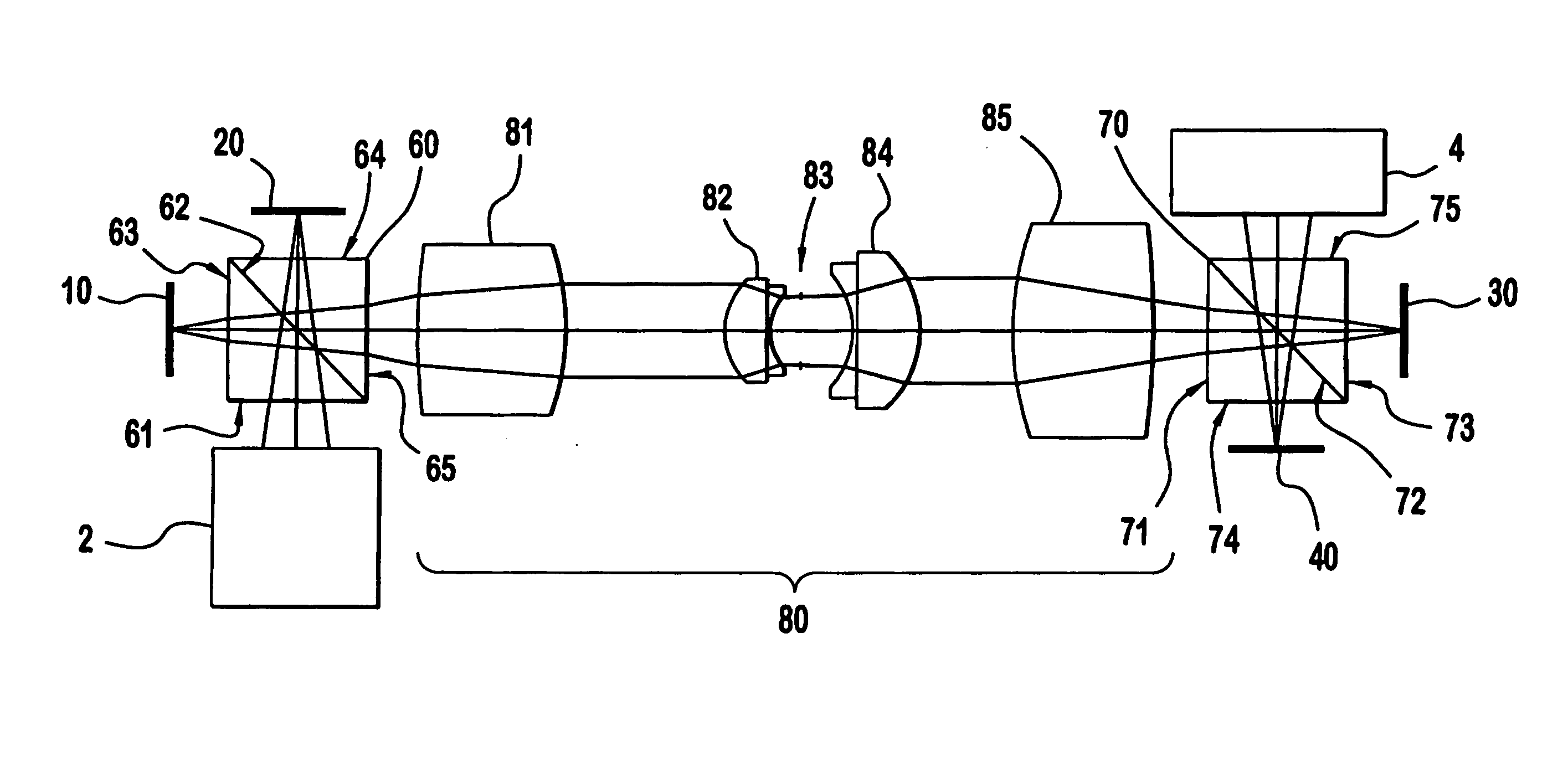
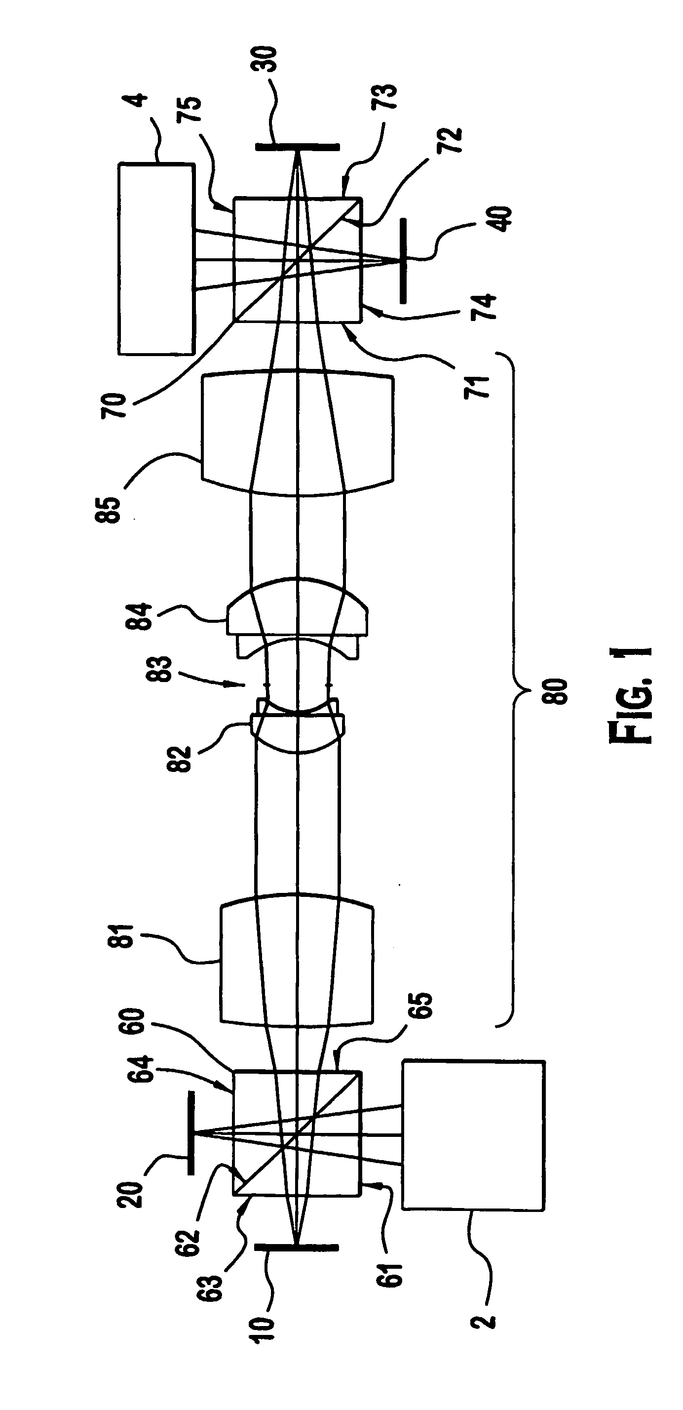
[0014] The present invention provides a two stage stereoscopic projection system. In an exemplary embodiment of the present invention, illustrated in FIG. 1, a two stage stereoscopic projection system comprises two first stage imagers 10, 20 and two second stage imagers 30, 40. The first stage imagers 10, 20 comprise a first channel first stage imager 10 and a second channel first stage imager 20, which are positioned proximate a first polarizing beam splitter 60 to receive oppositely polarized light beams and configured to modulate the polarized light beams to provide matrices of polarized light pixels. The second stage imagers 30, 40 comprise a first channel second stage imager 30 and a second channel second stage imager 40 positioned proximate a second polarizing beam splitter 70, and used to boost the contrast of the matrices of polarized light pixels from the corresponding first stage imagers 10, 20 by dynamically modulating each polarization or channel a second time, thereby c...


PUM


Abstract

A stereoscopic projection system is provided having two channels, each having two LCOS imagers that modulate light on a pixel-by pixel basis. A first polarizing beam splitter is configured to direct light of a first polarization onto a first channel first stage LCOS imager and direct light of a second polarization, opposite the first polarization, onto a second channel first stage LCOS imager. A relay lens system directs the output of the first stage imagers into a second polarizing beam splitter. The second polarizing beam splitter is configured to direct light of the second polarization onto the first channel second stage LCOS imager and direct light of the first polarization onto the second channel second stage LCOS imager.

Description

CROSS-REFERENCE TO RELATED APPLICATIONS [0001] This application claims the benefit of U.S. Provisional Patent Application Ser. No. 60 / 430,896 (Atty. Docket No. PU020472), entitled “HIGH CONTRAST STEREOSCOPIC PROJECTION SYSTEM”, filed Dec. 4, 2002, which is incorporated by reference herein in its entirety.FIELD OF THE INVENTION [0002] The present invention relates generally to optical projection systems and more particularly to a high contrast stereoscopic projection system. BACKGROUND OF THE INVENTION [0003] Liquid crystal displays (LCDs), and particularly liquid crystal on silicon (LCOS) systems using a reflective light engine or imager, are becoming increasingly prevalent in imaging devices such as rear projection television (RPTV). In an LCOS system, projected light is polarized by a polarizing beam splitter (PBS) and directed onto a LCOS imager or light engine comprising a matrix of pixels. Throughout this specification, and consistent with the practice of the relevant art, the ...

Claims


Application Information

Patent Timeline
IPC IPC(8): G03B21/00G02B30/25H04N5/74H04N13/363
CPCH04N5/7441H04N9/3126H04N13/0434H04N13/0459H04N13/337H04N13/363H04N5/74H04N13/00G02F1/1347
Inventor DRAZIC, VALTERHALL JR, ESTILL THONEO'DONNELL, EUGENE MURPHY
Owner INTERDIGITAL CE PATENT HLDG
Why Eureka
Try Eureka