Luminance-enhancing polarising plate for an organic light-emitting element

Active Publication Date: 2010-12-23
LG CHEM LTD
View PDF7 Cites 40 Cited by
  • Summary
  • Abstract
  • Description
  • Claims
  • Application Information

AI Technical Summary

Benefits of technology

[0013]The polarizer for OLED according to one exemplary embodiment of the present invention may be useful to enhance a contrast ratio of the OLED and highly improve the brightness as well by disposing a reflective polarizer film between the linear polarizer and the ¼ retardation plate, the reflective polarizer film being able to selectively transmit a linearly polarized light.
[0014]Also, the polarizer for OLED according to one exemplary embodiment of the present invention may be useful to decrease the reflectance of external light in order to improve the contrast ratio of the OLED by forming an adhesive layer on the top or bottom of the reflective polarizer film, the adhesive layer being formed of a color compensation adhesive and including a light absorbing agent.

Problems solved by technology

This internal reflection causes problems associated with the degradations in contrast and visibility of the OLED.
However, the conventional circular polarizer has a problem in that, although it is used to improve the contrast, its transmittance is dropped by below 45% due to the absorption of light by the circular polarizer, which leads to the significantly degraded brightness of the OLED.
Light emitted from the emissive layer of the OLED may be reduced in brightness by the reflection (i.e. total internal reflection) while being passed through the hole transport layer, the hole injecting layer, the anode and the transparent substrate, and be finally reduced in brightness by 10% or less while being passed through the circular polarizer, which leads to low light emission efficiency.
In order to solve these problems regarding the degraded brightness, a method of optically modifying a transmission path inwards the OLED device or using special substances at respective layers has been under consideration, but this alternative method has problems in that it is difficult to be put to practical use due to the inefficient process and low yield, and thus due to high manufacturing costs.

Method used


Image

  • Luminance-enhancing polarising plate for an organic light-emitting element
  • Luminance-enhancing polarising plate for an organic light-emitting element
  • Luminance-enhancing polarising plate for an organic light-emitting element

Examples


example 1

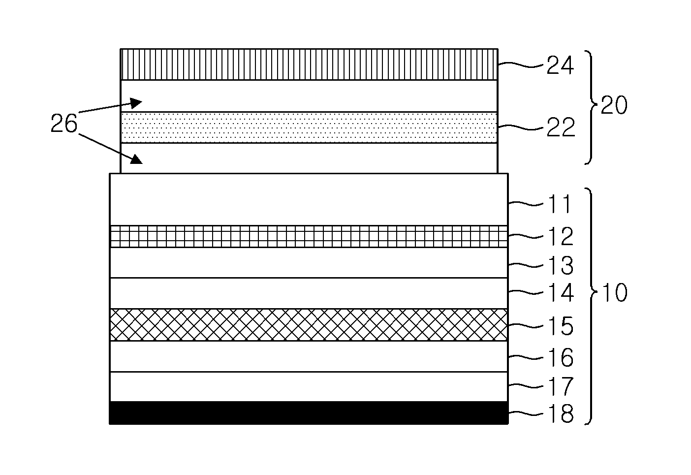
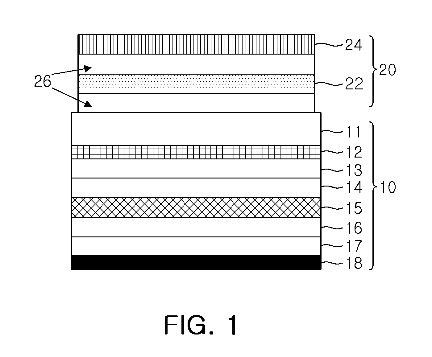
[0039]A conventional linear polarizer, which was obtained by stacking TAC protective films on upper and lower surfaces of a polyvinyl alcohol (PVA) film, was used as a base film. Then, the polarizer having improved brightness according to one exemplary embodiment of the present invention was prepared by sequentially attaching a reflective polarizer film (brightness-improving film, 3M) and a 140 nm-thick ¼ wavelength retardation film (a COP elongation film having a normal dispersion characteristic) to a lower surface of the conventional linear polarizer. Here, the reflective polarizer film might transmit a certain linearly polarized light at a transmittance level of 50%. Then, the prepared polarizer was attached to an OLED panel (a 2-inch passive matrix-type OLED panel).

example 2

[0040]A conventional linear polarizer, which was obtained by stacking TAC protective films on upper and lower surfaces of a PVA film, was used as a base film. Then, a reflective polarizer film (brightness-improving film, 3M) that might transmit a certain linearly polarized light at a transmittance level of 50% was attached to a lower surface of the conventional linear polarizer. Then, a color compensation adhesive whose transmittance is adjusted to a level of 80% was prepared by adding a black dye to an acryl-based adhesive (a mixing ratio=100:0.02), and the reflective polarizer film was coated with the color compensation adhesive to form a color compensation adhesive layer. Then, a 140 nm-thick ¼ wavelength retardation film (a COP elongation film having a normal dispersion characteristic) was attached onto the color compensation adhesive layer to prepare a polarizer having improved brightness according to one exemplary embodiment of the present invention. Finally, the prepared pola...

experimental example 1

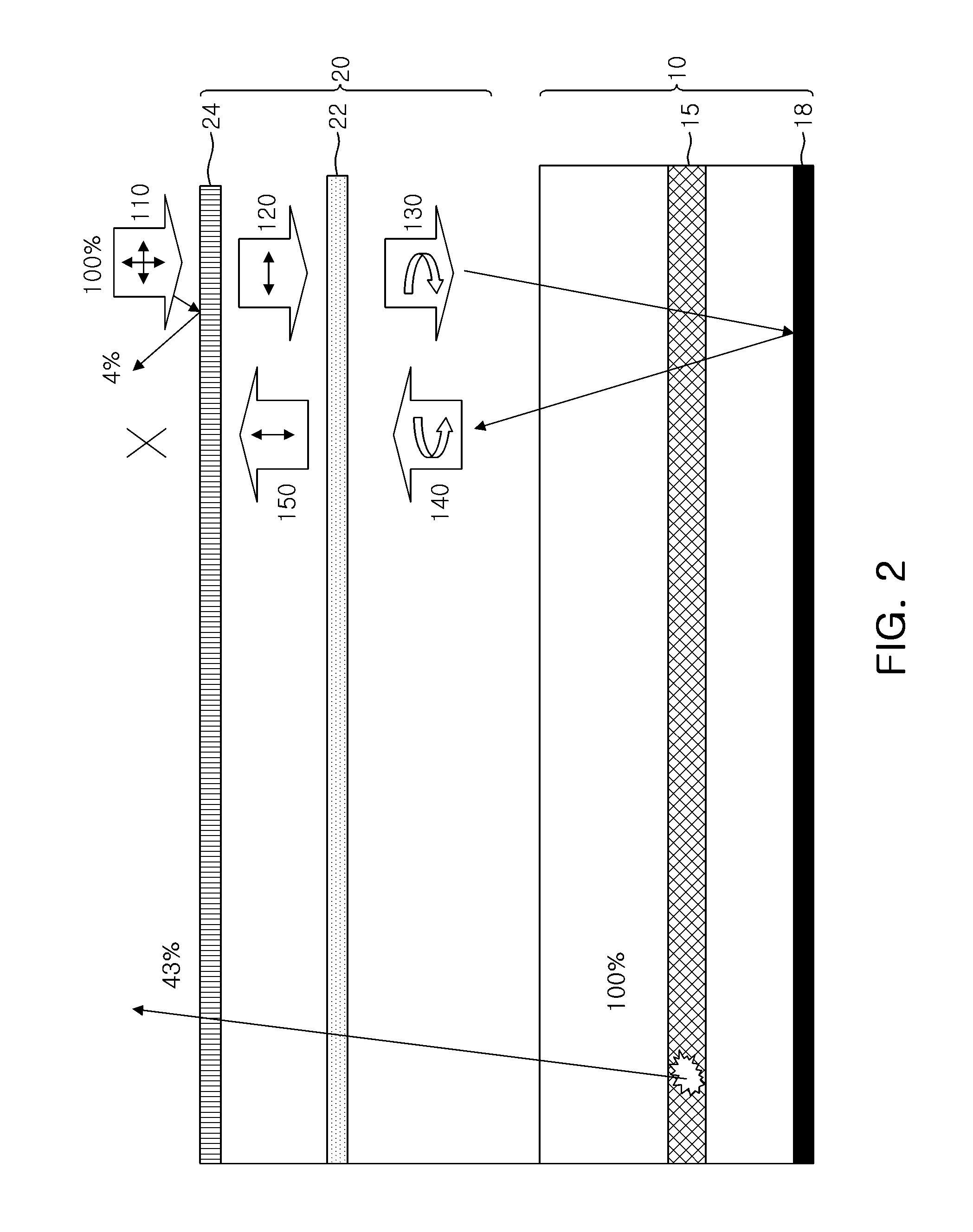
[0043]The OLED panels prepared in Examples 1 to 2 and Comparative examples 1 and 2 were measured for brightness and reflectance.

[0044]The brightness was calculated after the intensity of light emitted during the driving of each OLED panel was measured according to the wavelengths. Here, the brightness ratios of the OLEDs were listed in the parentheses, provided that it was assumed that the intensity of light emitted from the OLED panel (Comparative example 1) to which the polarizer was not attached was 100%.

[0045]Meanwhile, the reflectance was calculated by measuring the intensity of light reflected on the front side of each OLED panel using a UV spectrometer. Here, the reflectance ratios of the OLEDs were listed in the parentheses, provided that it was assumed that the reflectance of the OLED panel (Comparative example 1) to which the polarizer was not attached was 100%.

[0046]The measurement results are listed in the following Table 1.

TABLE 1Brightness, cd / A (%)Reflectance, AU (%)C...


PUM


Abstract

There is provided a polarizer for organic light emitting diodes (OLED) having improved brightness. The polarizer, which comprises a linear polarizer and a ¼ retardation plate, comprises a reflective polarizer film disposed between the linear polarizer and the ¼ retardation plate and transmitting a polarized light horizontal to the transmission axis of the linear polarizer while reflecting a polarized light vertical to the transmission axis of the linear polarizer. The polarizer may be useful to highly improve the brightness of the OLED device when the polarizer is used in the OLED device.

Description

TECHNICAL FIELD[0001]The present invention relates to a polarizer for organic light emitting diodes (OLED), and more particularly, to a polarizer that is developed to highly improve the brightness of the OLED.BACKGROUND ART[0002]An organic light emitting diode (OLED) refers to ‘a spontaneously light-emitting organic material’ that emits light by using electroluminescence where a fluorescent organic compound is allowed to emit light when an electric current is applied to the fluorescent organic compound. This OLED may be driven at a relatively low voltage and manufactured with a small thickness, and has a wide viewing angle and a swift response time as well. Therefore, the OLED has advantages in that, unlike the liquid crystal displays (LCD), it has an unchanged image quality and no image sticking even when seen right by the side, and may realize its full coloration as well. Therefore, the OLED has a high potential as one of leading devices of the next-generation flat panel display.[...

Claims


Application Information

Patent Timeline
IPC IPC(8): H01L33/58G02B27/28
CPCG02B5/3033H01L51/5262H01L51/5281H01L51/5293H01L33/58H01L51/50G02B27/28G02B5/30H10K50/85H10K50/86H05B33/10H10K50/00H10K50/868
Inventor KIM, SIN-YOUNGYOON, HYUKPARK, MOON-SOOSERGEY, BELYAEV
Owner LG CHEM LTD
Why Eureka
Try Eureka