Bearing mechanism, carriage assembly, and magnetic disk drive

a technology of bearing mechanism and magnetic disk drive, which is applied in the direction of mechanical equipment, record information storage, instruments, etc., can solve the problems of inability to accurately position the magnetic head, and achieve the effect of lowering the height, reducing the height, and thinning the structur

Inactive Publication Date: 2006-04-20
WESTERN DIGITAL TECH INC
View PDF3 Cites 8 Cited by
  • Summary
  • Abstract
  • Description
  • Claims
  • Application Information

AI Technical Summary

Benefits of technology

[0024] According to the present invention, a bearing mechanism for lowering the height, a carriage assembly for lowering the height, and a magnetic disk drive for achieving a thinner structure can be provided.

Problems solved by technology

Specifically, if a natural frequency of the carriage is low, the carriage resonates during operation, thus becoming unable to accurately position the magnetic head.

Method used


Image

  • Bearing mechanism, carriage assembly, and magnetic disk drive
  • Bearing mechanism, carriage assembly, and magnetic disk drive
  • Bearing mechanism, carriage assembly, and magnetic disk drive

Examples


Embodiment Construction

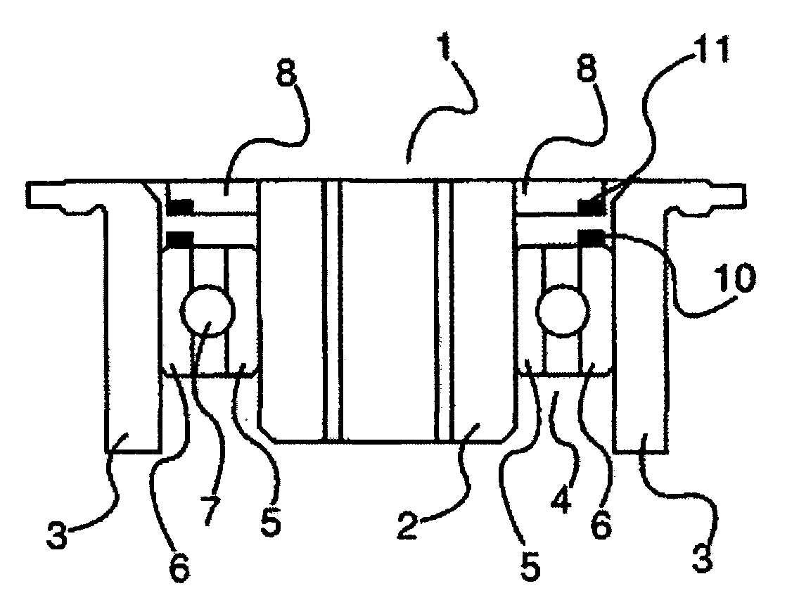
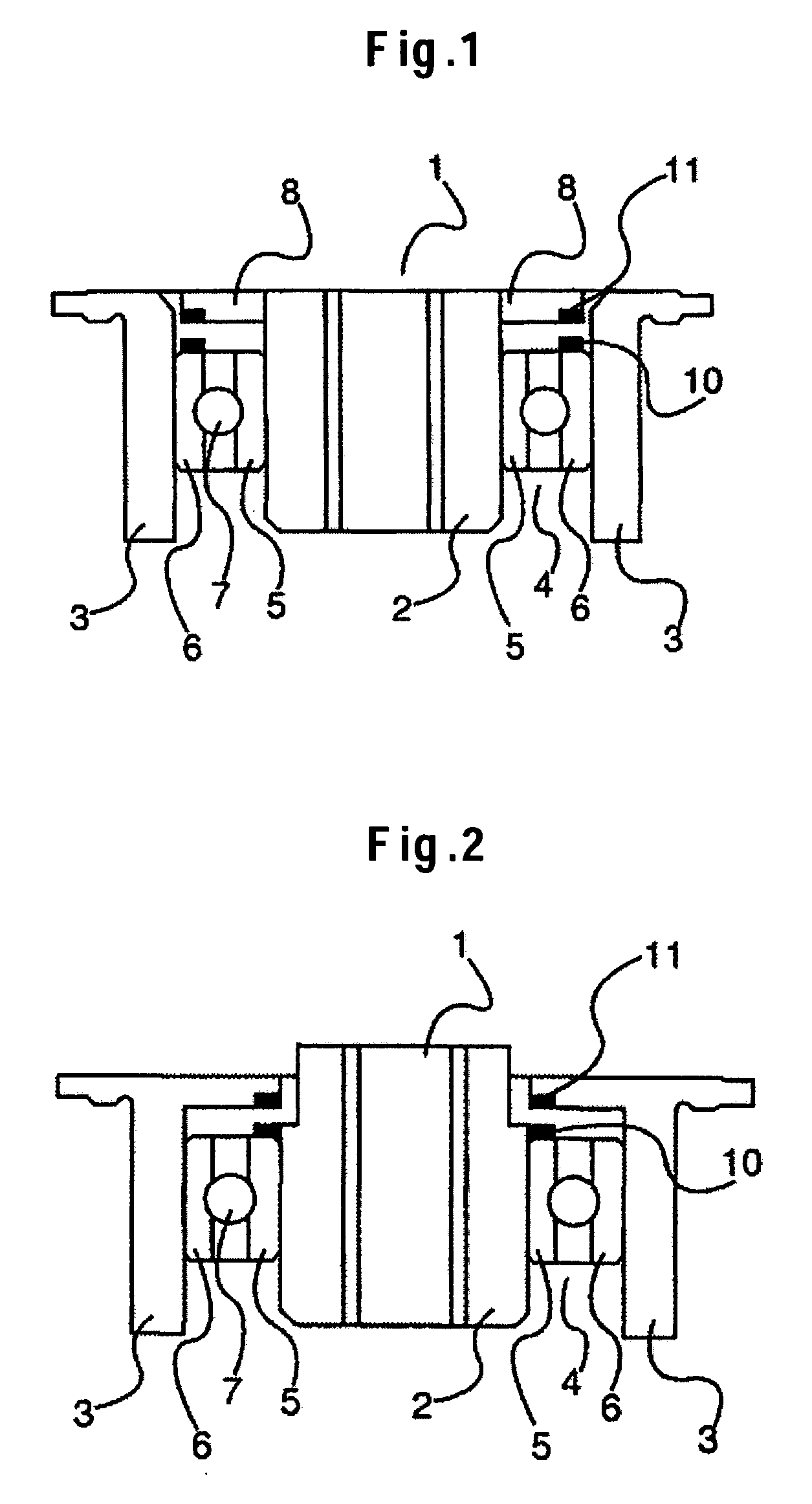
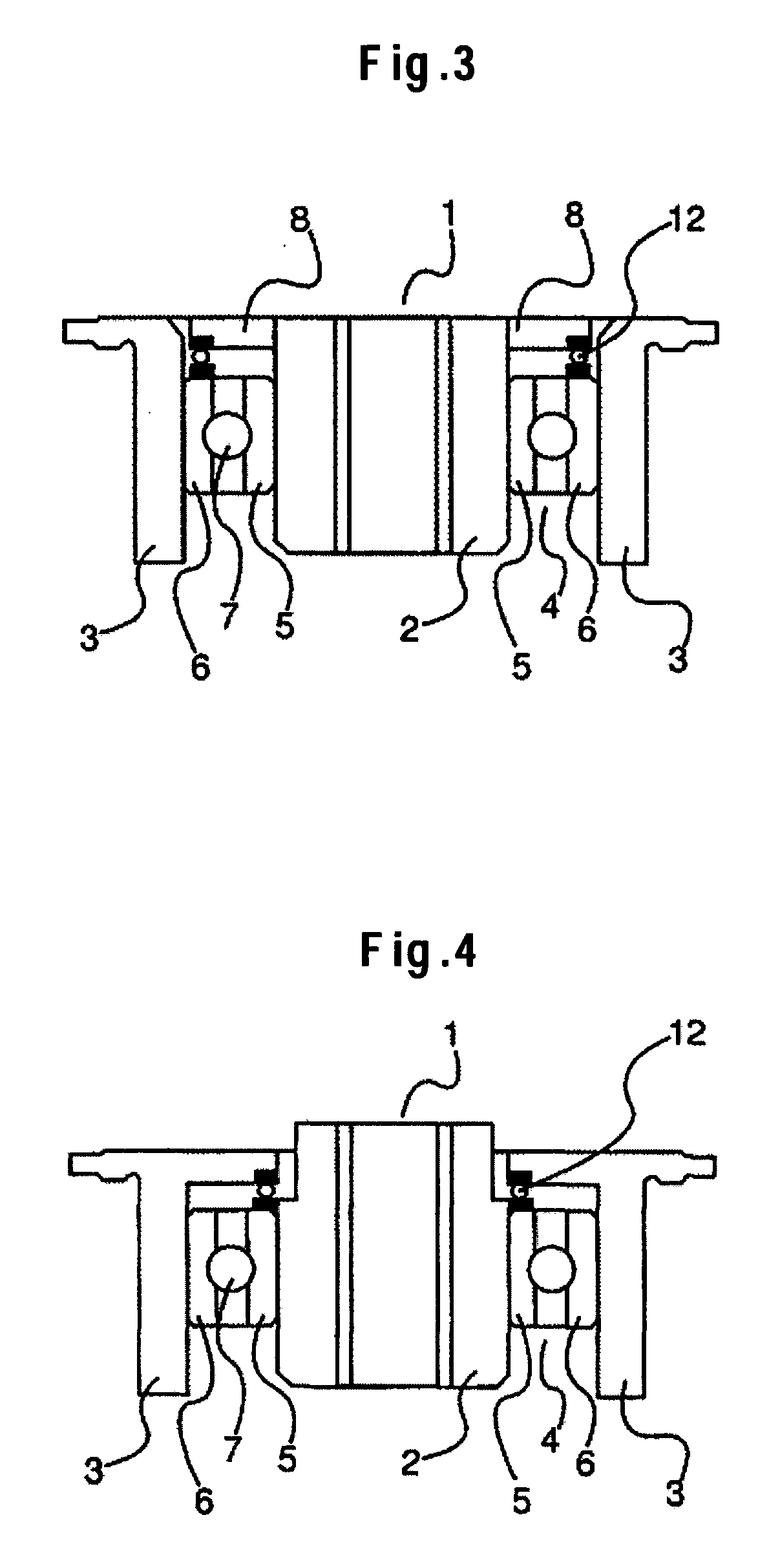
[0031] A structure of a magnetic disk drive 20 mounted with a carriage assembly using a bearing mechanism (a pivot bearing) according to the present invention will be described with reference to FIG. 5. FIG. 5 is a perspective view showing the magnetic disk drive 20 with a cover thereof removed. A spindle motor 22 is secured to a base 21. A magnetic disk 23 is mounted on a rotating shaft of the spindle motor 22. A pivot bearing 1 is attached to the base 21. A head arm 24 and a coil 27 are mounted on the pivot bearing 1. A suspension 25 is mounted to the head arm 24. A magnetic head 26 is fitted to a leading end of the suspension 25. A magnetic circuit 28 forming part of a voice coil motor (an actuator) is provided for the base 21 so as to sandwich the coil 27. When current is passed through the coil 27, a thrust force is generated in the coil 27, causing the head arm 24 to make a rotatable motion about the pivot bearing 1. This positions the magnetic head 26 attached to the leading ...


PUM


Abstract

Embodiments of the invention are directed to keeping a height of a pivot bearing low in order to build a thinner magnetic disk drive. In one embodiment, a ball bearing is provided between a shaft and a sleeve. An inner race of the ball bearing is secured to the shaft through bonding or the like. An outer race of the ball bearing is secured to the sleeve through bonding or the like. A bearing ball is placed between the inner race and the outer race of the ball bearing. A magnet is fitted to the outer race of the ball bearing. A magnet is mounted on a circular plate mounted on one end of the shaft. The magnet is located at a position opposing the magnet mounted on the outer race so as to generate a repulsive force therebetween.

Description

CROSS-REFERENCES TO RELATED APPLICATIONS [0001] This application claims priority from Japanese Patent Application No. JP2004-299701, filed Oct. 14, 2004, the entire disclosure of which is incorporated herein by reference. BACKGROUND OF THE INVENTION [0002] The present invention relates generally to a bearing mechanism, a carriage assembly having a head arm mounted on a bearing mechanism, and a magnetic disk drive mounted with a carriage assembly, and more particularly, to a structure of a bearing mechanism. [0003] A magnetic disk drive includes a spindle motor portion, a carriage portion, an actuator portion, and a base and cover portion. The spindle motor portion includes a magnetic disk secured onto a spindle hub by means of a disk clamp. The carriage portion includes a pivot bearing for rotatably moving a magnetic head, which is supported by a suspension mounted on a head arm, to any desired position on the magnetic disk. The actuator portion includes a magnetic circuit for drivi...

Claims


Application Information

Patent Timeline
Patent Type & Authority Applications(United States)
IPC IPC(8): F16C19/00
CPCF16C23/08G11B5/5569H02K7/08H02K7/09
Inventor OKUMURA, TADASHI
Owner WESTERN DIGITAL TECH INC
Why Eureka
Try Eureka