Image-forming device

a technology of image-forming device and forming device, which is applied in the direction of electrographic process apparatus, instruments, optics, etc., can solve the problems of insufficient arrangement and constant reduction of forming device, and achieve the effect of insufficient compactness

Active Publication Date: 2006-04-20
BROTHER KOGYO KK
View PDF9 Cites 21 Cited by
  • Summary
  • Abstract
  • Description
  • Claims
  • Application Information

AI Technical Summary

Benefits of technology

[0007] In view of the foregoing, it is an object of the present invention to provide an image-forming device having equipped with an image-reading unit for reading image data from an original document and configured so as to be sufficiently compact.

Problems solved by technology

However, recent image-forming devices are continually being made smaller, with particular emphasis on a compact body.
Such an arrangement is insufficient for producing a compact image-forming device.

Method used


Image

  • Image-forming device
  • Image-forming device
  • Image-forming device

Examples


Embodiment Construction

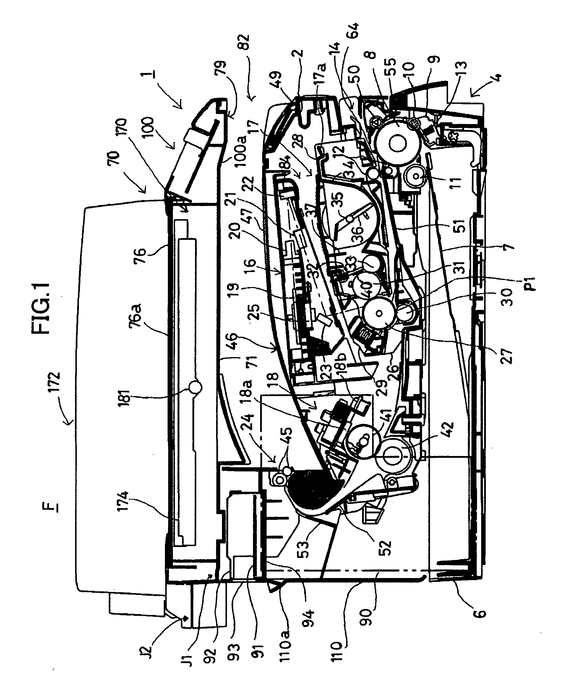
[0018] An image-forming device according to the present invention will be described while referring to FIGS. 1 through 6.

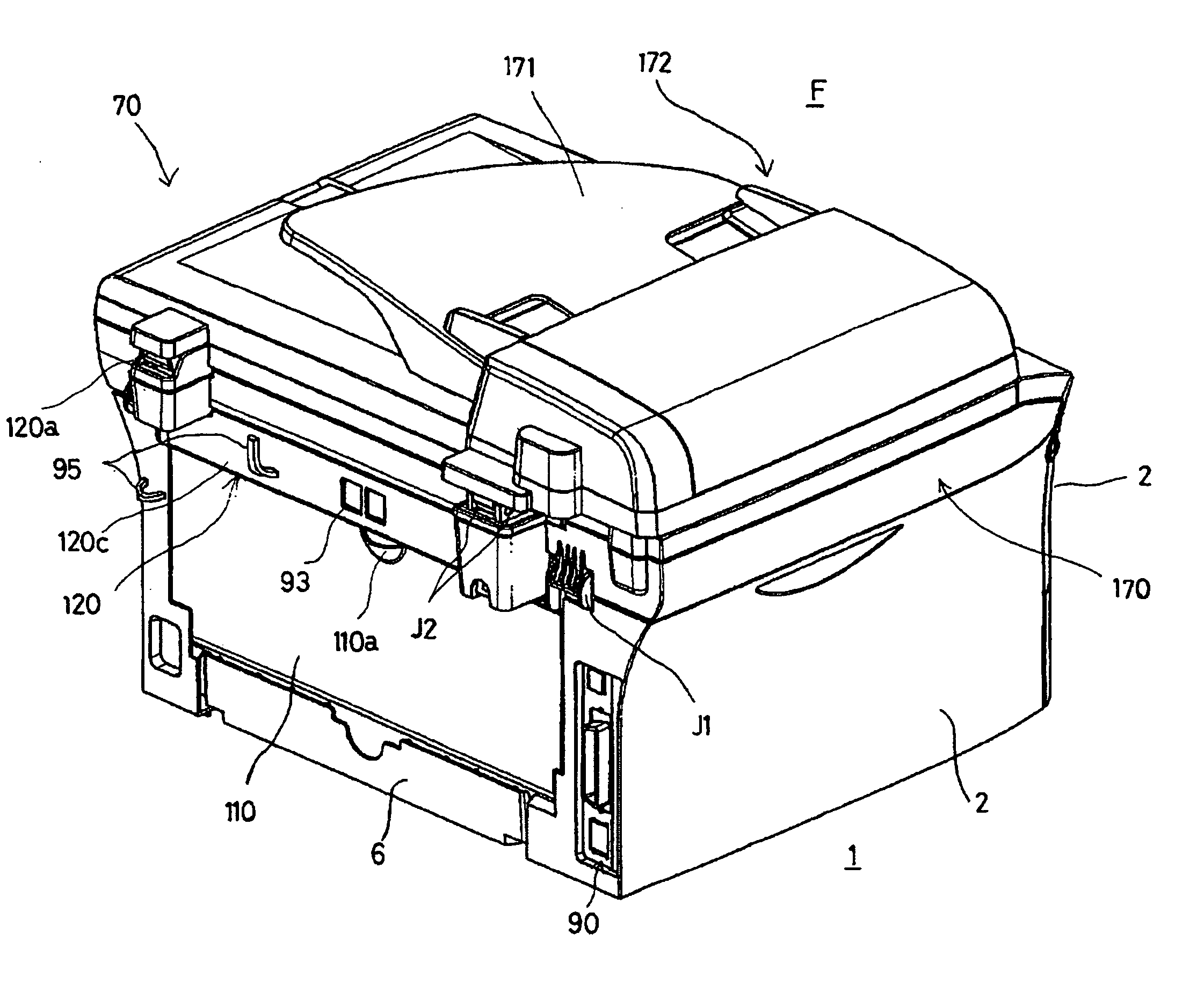
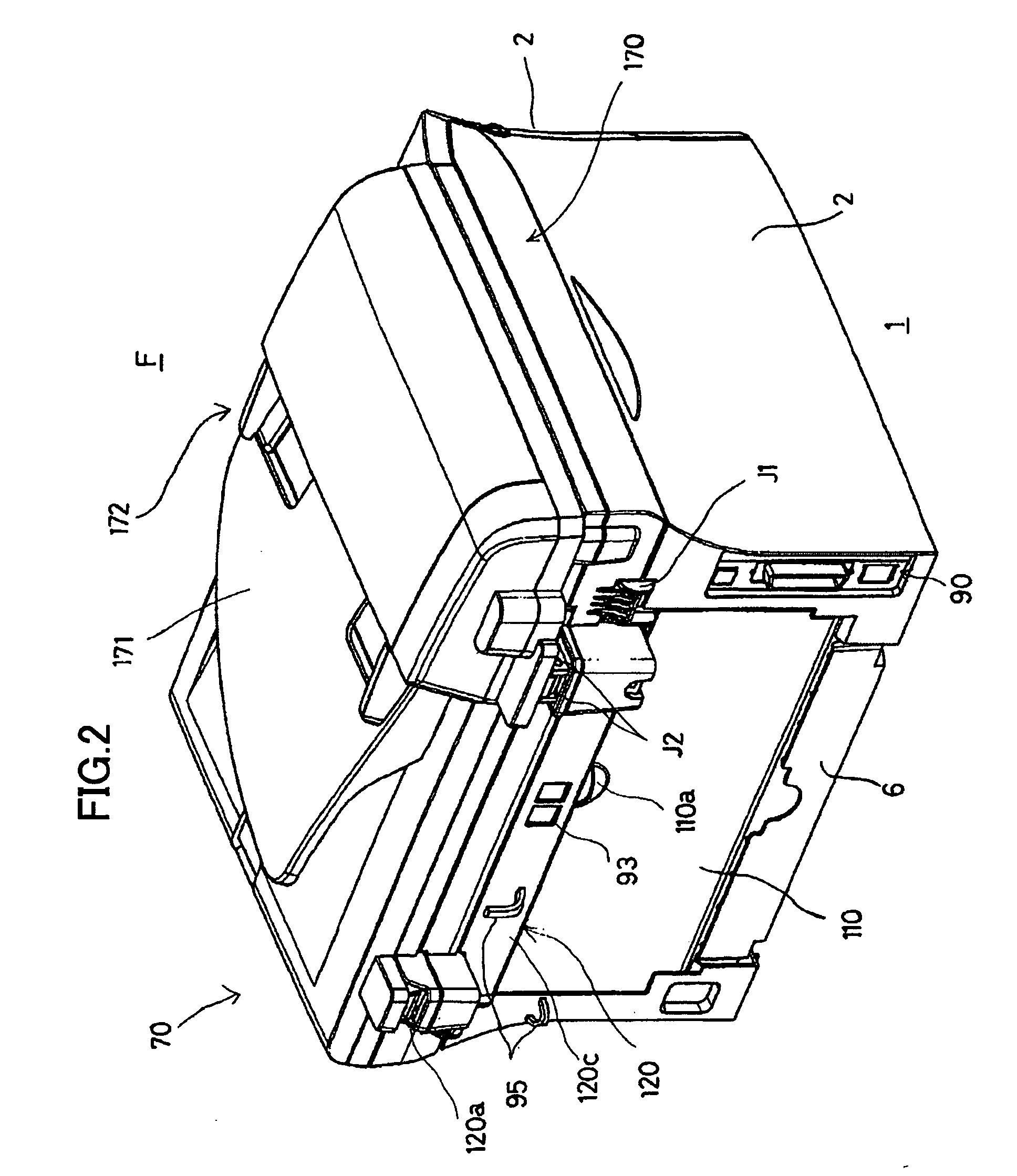
[0019] Referring to FIG. 1, a multifunction device F includes an image-forming unit 1 for forming prescribed images on a paper 3; and a flatbed scanning unit 70 that is mounted on the image-forming unit 1. The multifunction device F is provided with a printer function to form an image on the paper 3, a scanning function to read an image from an original document, a copier function to make a copy of an image, and facsimile function to transmit and receive an image through a network.

[0020] Overall Structure

[0021] First, the general structure of the multifunction device F will be described with reference to FIG. 1. In FIG. 1, the multifunction device F is viewed along the axial direction of various rollers described later. In the following description, the right side of FIG. 1 is referred to as a forward direction of the device F, while the left side of FIG. 1 is ...


PUM


Abstract

A multifunction device includes a scanning unit, an image-forming unit, and a joint holder for supporting the scanning unit on top of the image-forming unit. The joint holder is configured of a rear holder disposed on the upper rear side of the image-forming unit and two side holders disposed on top of the image-forming unit on the left and right sides for supporting the scanning unit on three sides. A network control unit is accommodated in an internal space in the rear holder, while a backup battery and a speaker are accommodated in internal spaces in the side holders. Accordingly, the multifunction device is downsized.

Description

BACKGROUND OF THE INVENTION [0001] 1. Technical Field [0002] The present invention relates to an image-forming device equipped with an image-reading unit for reading image data from an original document. [0003] 2. Related Art [0004] Proposals have been made for image-forming devices having a basic function and the capability of adding expanded functions as needed. One such image-forming device is disclosed in Japanese patent application publication No. HEI-10-20596. FIG. 7 shows an example of the image-forming device disclosed in this publication. As shown in FIG. 7, the image-forming device includes an engine section 211, and a stacked paper-delivery section 212 disposed on top of the engine section 211. When adding a printer function and facsimile function, a scanner unit 213 is disposed on top of the stacked paper-delivery section 212; and an expansion board accommodating unit 241 is provided between the engine section 211 and the scanner unit 213 in parallel with the stacked pap...

Claims


Application Information

Patent Timeline
Patent Type & Authority Applications(United States)
IPC IPC(8): G03G15/00
CPCG03G15/605G03G2215/00316
Inventor ITO, SAKAE
Owner BROTHER KOGYO KK
Why Eureka
Try Eureka