Antivibration device having rotary flyweights and an epicyclic geartrain

a technology of epicyclic geartrain and anti-vibration device, which is applied in the direction of anti-hunting elements, rotocraft, toothed gearings, etc., can solve the problems of reducing the comfort of the occupants of the structure, reducing the overall size of the device, and reducing the size of the device. , the effect of minimizing the size of the devi

Active Publication Date: 2008-03-25
EUROCOPTER +1
View PDF7 Cites 8 Cited by
  • Summary
  • Abstract
  • Description
  • Claims
  • Application Information

AI Technical Summary

Benefits of technology

[0011]An object of the present invention is to propose an antivibration device with rotary flyweights that is accurate, robust, and sufficiently compact to enable it to be installed in a restricted space such as a rotorcraft cabin.
[0013]As explained below, the angular phase difference between the flyweights of the second set relative to the flyweights of the first set is not modified by moving the main motor in linear translation, and that makes it possible to optimize the compactness of the device.
[0014]In addition, since the two rotors in each set are disposed symmetrically about a longitudinal axis of symmetry, the main motor is arranged inside the rectangular parallelogram along the axis of symmetry. This disposition makes the device correspondingly more compact.
[0020]The phase-shifter means is rotary and comprises at least one second planet gear arranged on a second planet carrier that is movable in rotation relative to the second end disposed between the second sun gear and the second outer ring gear. By using a stationary secondary motor to cause the second planet carrier to turn together with the associated second planet gear, with turning being either clockwise or counterclockwise, it is possible to decrease or increase the speed of rotation of the group comprising the second outer ring gear, the second orthogonal gear and the contra-rotary rotors with eccentric flyweights of the second set, thereby varying the angular phase difference between those flyweights and the eccentric flyweights of the first set.
[0023]Finally, the shape of the flyweights is also optimized so as to minimize the size of the device. Each set thus has one rotor with a thick flyweight provided with two identical disk portions separated by a groove, the other rotor then having a thin flyweight provided with a single disk portion of thickness slightly smaller than the width of said groove, the thin and thick flyweights naturally being identical in weight. Thus, the eccentric flyweights of the rotors of one set can overlap each other, thereby reducing the overall size of the device. Furthermore, the distance between the center of gravity of the thin flyweight and its axis of rotation is advantageously equal to the distance of said center of gravity of the thick flyweight and its axis of rotation.

Problems solved by technology

The rotation of each rotor produces a rotary unbalance.
Nevertheless, in the event of one of the motors breaking down, the sets cease to rotate at the same speed, which means that the resultant force is no longer under control.
Consequently, the comfort of the occupants of the structure is greatly degraded and can even become worse than in the absence of any antivibration treatment.
In addition, a breakdown of the motor or a break of the endless link causes the device to come to a complete stop and therefore does not make the situation any worse.
Nevertheless, for the device to be accurate, the movement in translation of the controllable moving equipment carrying the motor along the axis of symmetry needs to be extensive.
Unfortunately, since this movement in translation is directly linked to the diameter of the pulleys, the pulleys must be large in size.
Consequently, it becomes difficult to arrange that device in a small space, such as a rotorcraft cabin, insofar as the space it occupies is not thoroughly optimized.

Method used


Image

  • Antivibration device having rotary flyweights and an epicyclic geartrain
  • Antivibration device having rotary flyweights and an epicyclic geartrain
  • Antivibration device having rotary flyweights and an epicyclic geartrain

Examples


first embodiment

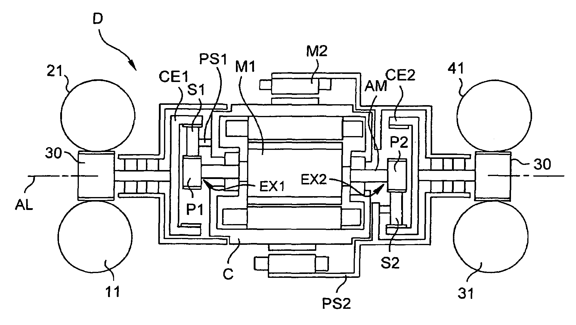
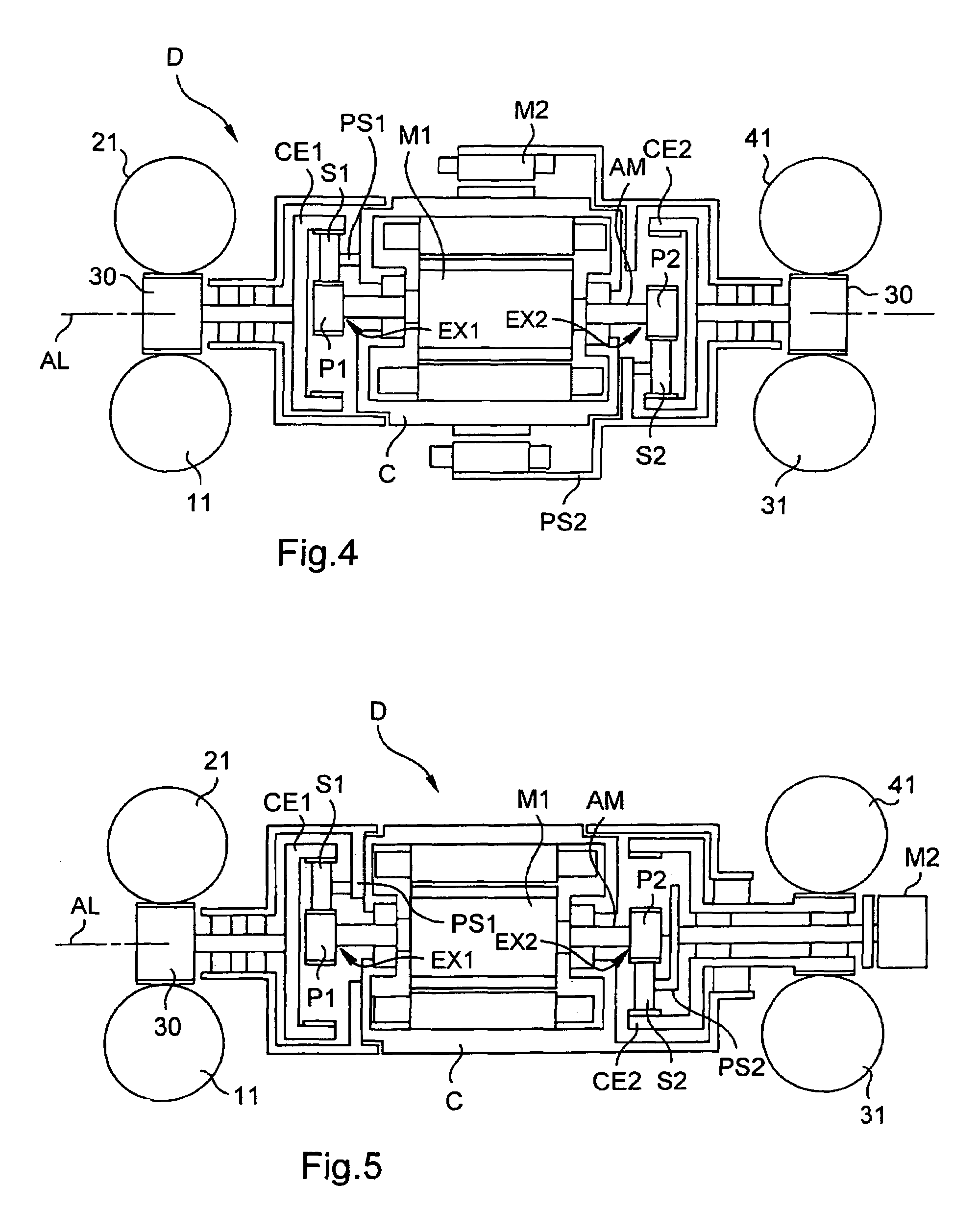
[0043]FIG. 4 shows the device D.

[0044]It comprises a casing C secured to a structure that is not shown. A main motor M1 secured to the casing C and disposed between the two sets E1 and E2 along the longitudinal axis of symmetry AL serves to rotate the rotors 11, 21, 31, and 41.

[0045]Consequently, a through shaft AM, provided with first and second sun gears P1 and P2 respectively at its first and second ends EX1 and EX2, passes through the main motor M1 along the longitudinal axis of symmetry AL.

[0046]The first sun gear P1 drives a first outer ring gear CE1 constrained to rotate with a first orthogonal gear 30 which transmits rotary motion to the rotors 11&21 with eccentric flyweights 12&22 of the first set E1. Since the speed of rotation of the main motor is high, speed-reducing gearing of the planet type is provided. This gearing comprises at least one first planet gear S1 arranged on a planet carrier PS1 that is stationary and secured to the casing C. The first planet gear S1 co-o...

second embodiment

[0056]With reference to FIG. 5, in a second embodiment, the main and secondary motors M1 and M2 are not concentric, but in line, i.e. they are disposed in succession along the longitudinal axis of symmetry AL.

[0057]Furthermore, sensors deliver signals relating to the phases of the flyweights and to the positions of the main and secondary motors M1 and M2 to a computer (not shown).

[0058]FIG. 6 is an isometric view showing clearly the compact nature of the device D.

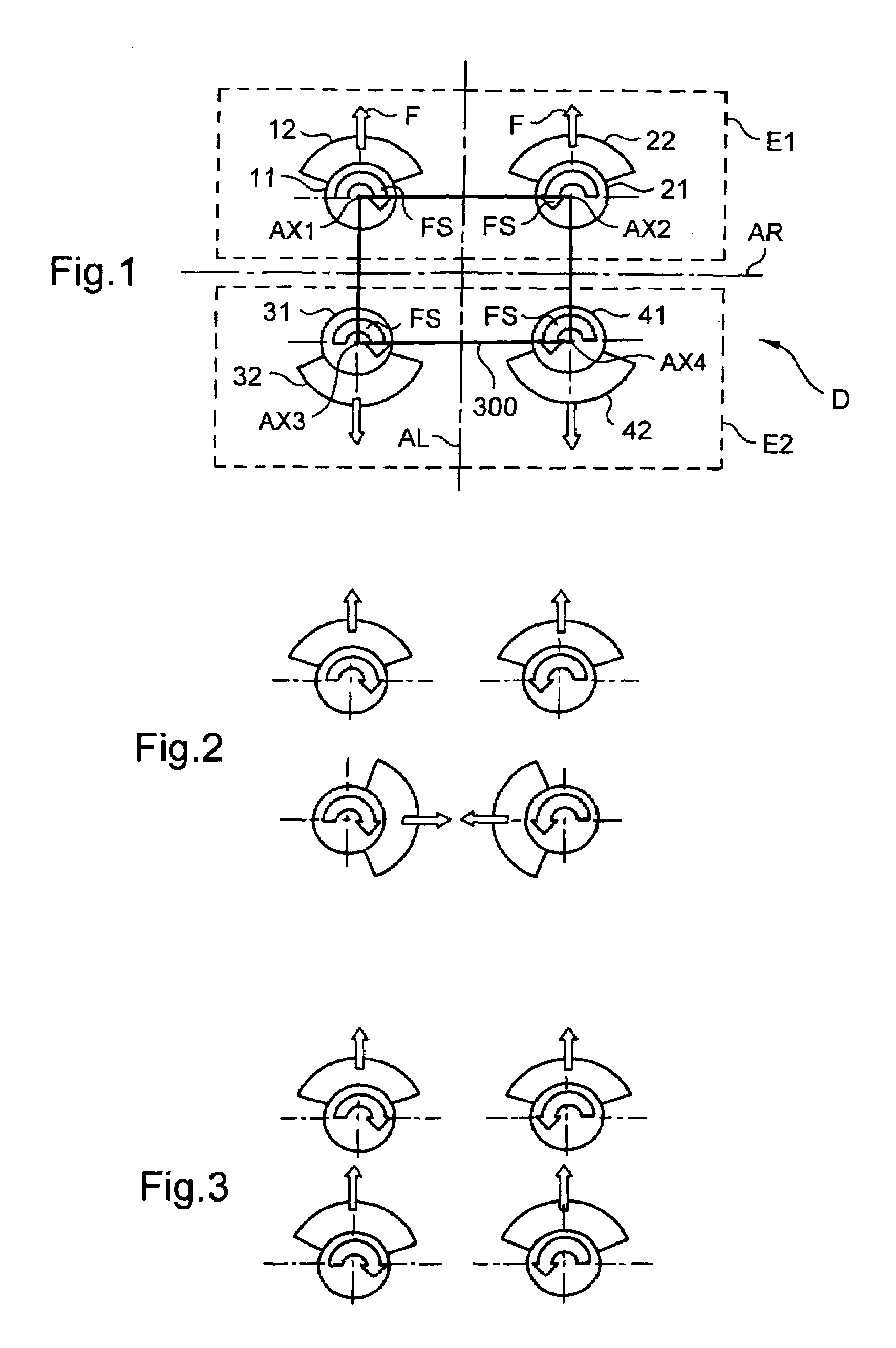
[0059]The four rotors 11, 21, 31, and 41 are positioned in the same second plane 200. Similarly, the associated eccentric flyweights 12, 22, 32, and 42 are positioned in the first plane 100.

[0060]Furthermore, the respective axes of rotation AX1, AX2, AX3, and AX4 of the rotors 11, 21, 31, and 41 are mutually parallel and orthogonal to the first and second planes 100 and 200.

[0061]The two rotors 11&21 and 31&41 in each set E1 and E2 are driven to rotate in opposite directions by an orthogonal gear 30. The axis of rotation of...


PUM


Abstract

An antivibration device for reducing the vibration of a structure, includes a stationary casing, mounted on the structure, and first and second sets each including two contra-rotary rotors having eccentric flyweights, the flyweights and the rotors being disposed respectively in first and second mutually parallel planes, the centers of rotation of the contra-rotary rotors representing the corners of a rectangular parallelogram in the second plane, and the axes of rotation of the contra-rotary rotors being mutually parallel and orthogonal to the first plane. In addition, it includes a stationary main motor secured to the casing with a through shaft having a first end driving the contra-rotary rotors of the first set and a second end driving the contra-rotary rotors of the second set.

Description

[0001]The present invention relates to an antivibration device of the centrifugal type suitable for use on board aircraft, for example, and in particular in the cabin of a rotorcraft. Nevertheless, the device can be made for any other application when it is desired to reduce or even eliminate vibration generated by a moving body.BACKGROUND OF THE INVENTION[0002]The vibration present in a rotorcraft cabin is due essentially to the rotation of the main rotor that provides propulsion and lift, and also to the flow of air along the fuselage of the rotorcraft.[0003]U.S. Pat. No. 5,903,077 discloses an antivibration device using eccentric flyweights to generate a force seeking to reduce the vibration of a structure. It comprises two sets of flyweights each provided with a motor which drives a pair of eccentric flyweight rotors, i.e. rotors having centers of gravity that are not situated on their axes of rotation. The rotation of each rotor produces a rotary unbalance. Thus, the device gen...

Claims


Application Information

Patent Timeline
Patent Type & Authority Patents(United States)
IPC IPC(8): F16H37/06F16H33/04
CPCB64C27/001F16F15/22B64C2027/004
Inventor MANFREDOTTI, THOMASQUESNE, PATRICK
Owner EUROCOPTER
Why Eureka
Try Eureka