

Shielded tamper and method of use for making aggregate columns
a technology of shielded tamper and aggregate column, which is applied in the direction of bulkhead/pile, construction, foundation engineering, etc., can solve the problems of sidewall collapse above the elevation of the shielded tamper head, collapse of pre-stressing, and prone to distortion of the formed column cavity,
- Summary
- Abstract
- Description
- Claims
- Application Information
AI Technical Summary
Benefits of technology
Problems solved by technology
Method used
Image

Examples
example i
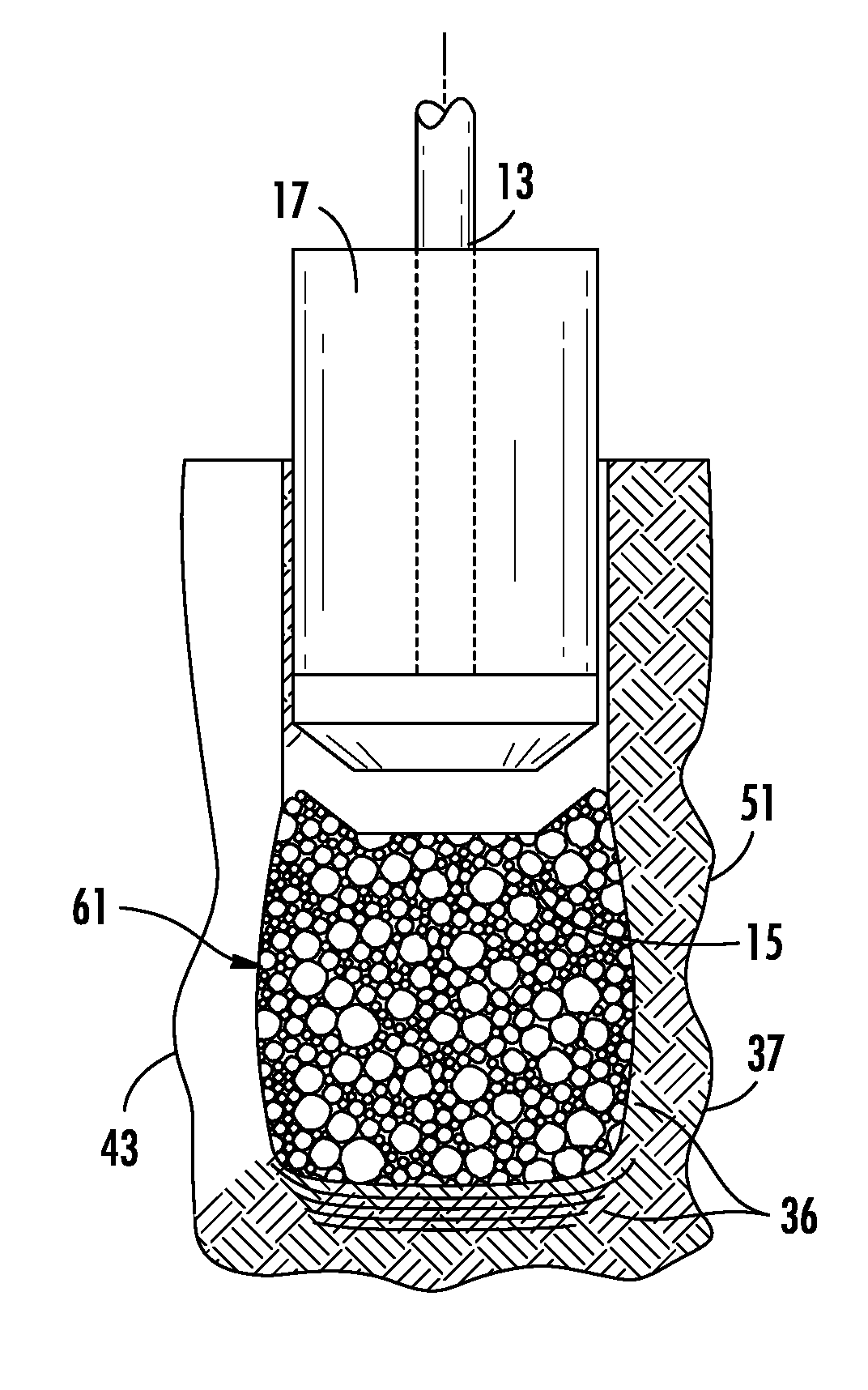
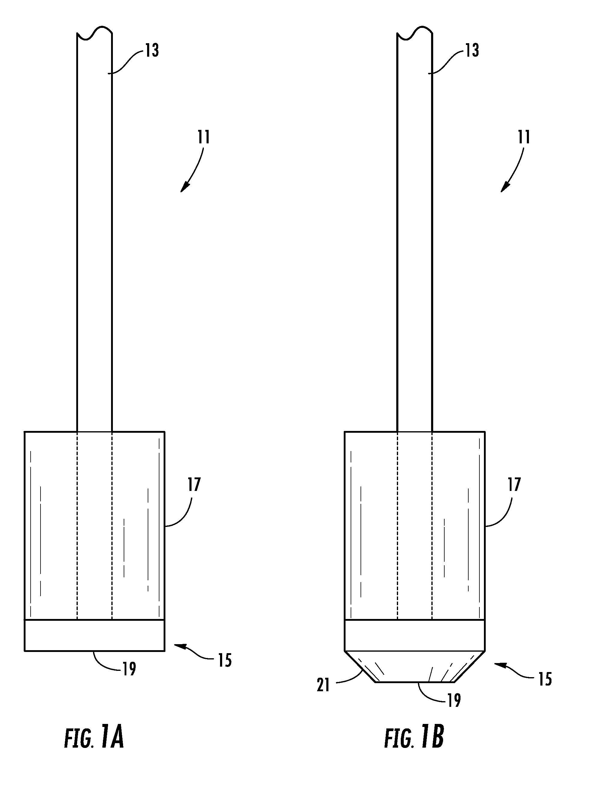
[0038]FIG. 6 illustrates the advantages described previously resulting from load tests conducted on columns constructed using a conventional process and using the present invention as will be discussed hereafter. The shielded tamper 11 used in the tests consisted essentially of that described above and shown in the attached Figures. In this example, the shielded tamper 11 was a 5-foot long, 18-inch diameter shield cylinder fitted on top of a beveled tamper head 15. The shield 17 was welded to the tamper head 15. A beveled perimeter 21 of the surface was tapered down at 45 degrees, from the upper end of the tamper head to a flat bottom surface.
[0039]For this testing, holes were drilled to a depth of 12 feet prior to backfilling with 1-inch minus crushed limestone. On the first day of testing, an 18-inch diameter hole was initially drilled, but it was determined that a hole with a diameter slightly larger than the shield cylinder would be preferable. As such, “cutters” were added to e...
example ii
[0048]As another example, the system of the invention was used to install columns at a Jackson Madison County Hospital site in Jackson, Tenn. Three columns were tested for this project: one with 1.5-foot thick loose lifts and 15-second tamping time per lift, one with 3.0-foot thick loose lifts and 20-second tamping time per lift, and one with 3.0-foot thick loose lifts and 30-second tamping time per lift. All three of the columns were installed with shaft lengths of 12 feet.
[0049]The subsurface conditions consisted of silty clay transitioning into sandy clay at a depth of about 7 feet, over clayey sand at approximately 10 feet, over sand at about 15 feet. SPT N-values ranged from 3 to 10 in the silty clay, increasing with depth; 11 in the sandy clay; 27 in the clayey sand; and 20 to refusal in the sand, again increasing with depth.
[0050]A 22-inch diameter shielded tamper head was used within a 24-inch diameter drilled hole.
[0051]A series of tests were performed to measure deflection...
example iii
[0053]As an additional example, the system including the tamper device 11 of the invention was used to install columns at a Tower Tech Systems site in Brandon, S.Dak. Test columns were located 12 and 24 feet south of the southernmost standard-constructed test column. The goal of this particular test was to make a direct comparison of the tamper device 11 of the present invention to a standard installed column using a conventional tool such as shown in U.S. Pat. No. 5,249,892.
[0054]The soil conditions at the site consisted of soft clay extending to 15.5 feet underlain by sand. SPT N-values in the clay within the reinforced zone ranged from 2 to 4 bpf. Moisture content ranged from 22 to 36%. Groundwater was located at a depth of about 9 feet.
[0055]Both 30-inch diameter standard columns and 20-inch diameter columns using an 18-inch diameter shielded tamper head were installed for testing at the site. The conventional 30-inch diameter test columns were extended to depths of 16 and 17.5 ...
PUM
 Abstract
Description
Claims
Application Information