Surgical punching instrument

a surgical and punching technology, applied in the field of surgical punching instruments, can solve the problems that the type of decomposability cannot be used in the case of bent right-angle punching shafts, and the type of decomposability cannot be used in the case of bent punching shafts

Active Publication Date: 2006-04-20
JORG WENZLER MEDIZINTECHN
View PDF5 Cites 68 Cited by
  • Summary
  • Abstract
  • Description
  • Claims
  • Application Information

AI Technical Summary

Benefits of technology

[0009] The basic object of the present invention is to provide a surgical punching instrument of the type mentioned in the introduction, but with instrument shafts bent at right angles, in which the instrument shafts comprising a punching slide and a punching bar each can be inserted into the guide part and can be removed therefrom in a simple manner, e.g., for cleaning purposes.
[0011] With the design according to the present invention, punch shafts bent at right angles can also be mounted snugly in the guide part, rotated, locked in different angular positions and removed in a simple manner. In addition, the design according to the present invention has the considerable advantage that the short lever arm of the actuating lever does not need to be mounted in a radially movable manner and does not need to be able to be removed from the path of motion of the plunger in order to make it possible to remove the punch shafts from the guide part.
[0013] Another advantage of the design according to the present invention is that it can be readily embodied with straight punch shafts.
[0014] Instead of the ball notch means provided in the case of the prior-art instruments, the design according to another aspect of the present invention has the considerable advantage that reliable securing of the punch shafts against rotation can be achieved with it relative to the tubular guide part and the handles, but this securing against rotation can also be easily released, by a corresponding actuation of the locking lever, in order to disengage the latter from the notches of the lever.
[0017] Due to the embodiment according to another aspect of the invention, it is also ensured with simple means that the two punch shafts do not separate from one another independently when they are removed from the guide part, and the embodiment according to claim 6 offers a simple possibility of removing the punching slide from the punching bar and to reattach it to same.
[0018] Another advantageous embodiment is provided according to another aspect of the invention. Due to this embodiment, the plunger can be separated from the punching slide in a simple manner, and it is also possible, to mount and remove the compression spring in a simple manner.

Problems solved by technology

This type of decomposability cannot be used in case of punch shafts bent at right angles.
This type of decomposability cannot be used in the case of punch shafts bent at right angles, either.

Method used


Image

  • Surgical punching instrument
  • Surgical punching instrument
  • Surgical punching instrument

Examples


Embodiment Construction

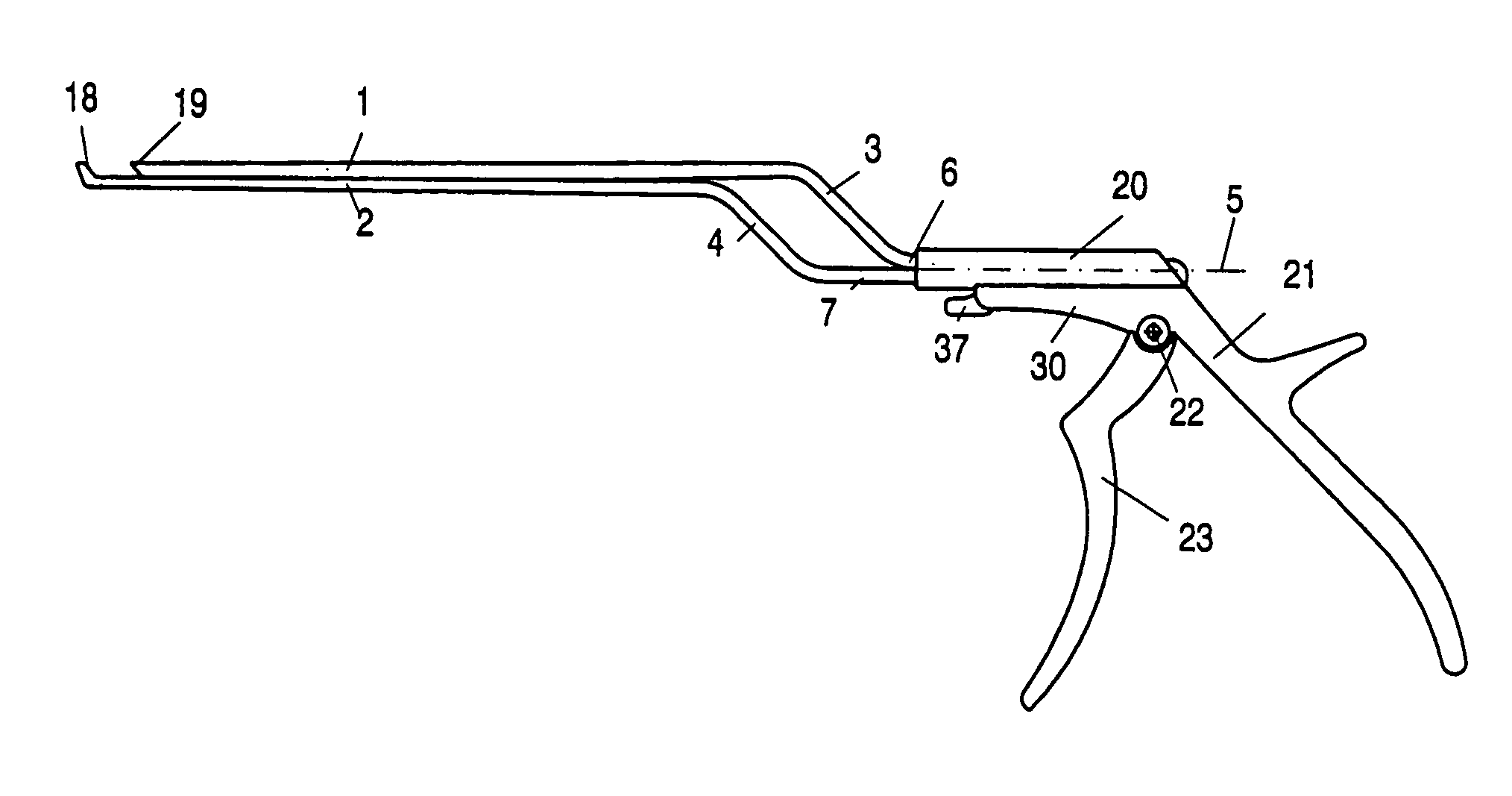
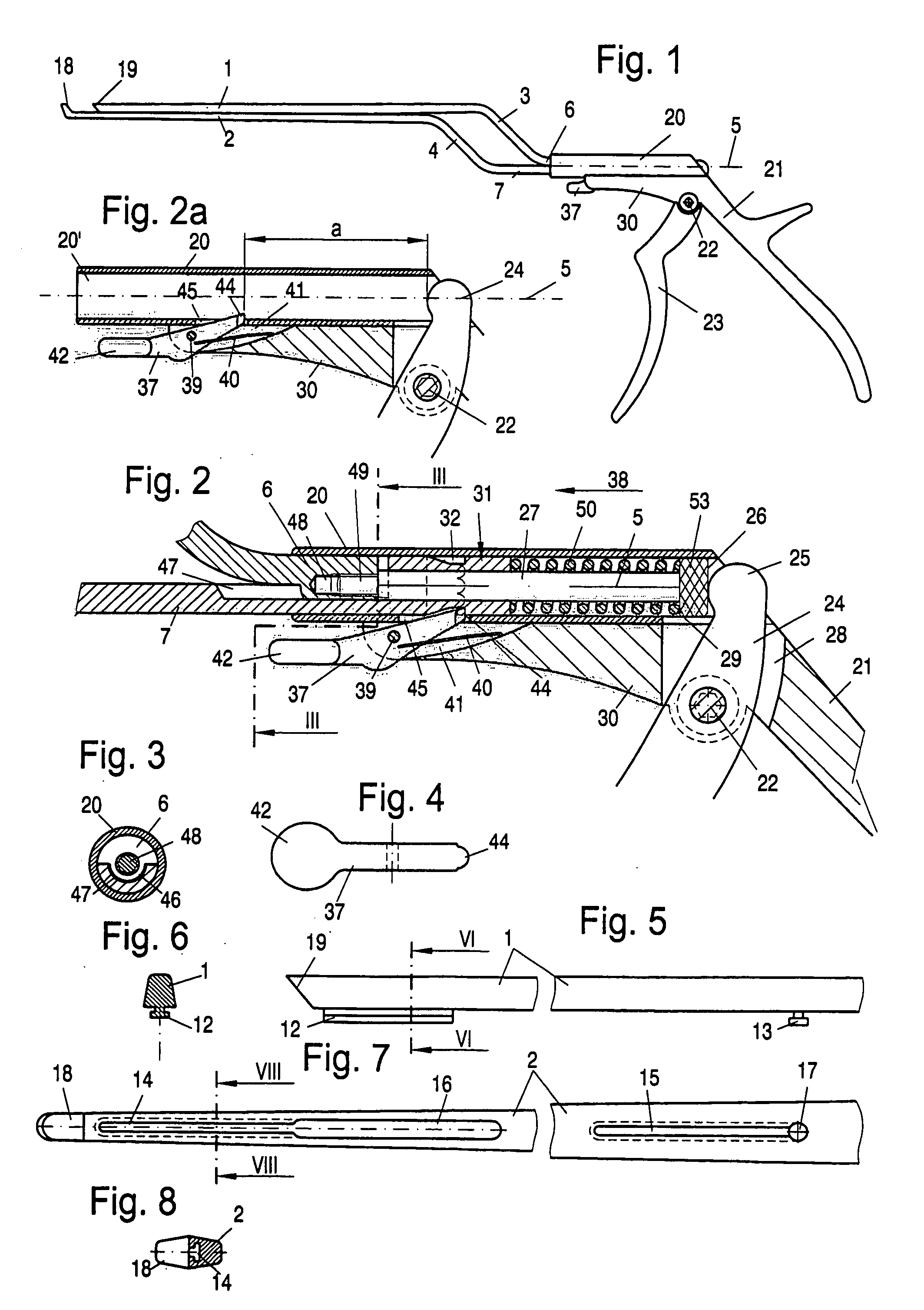
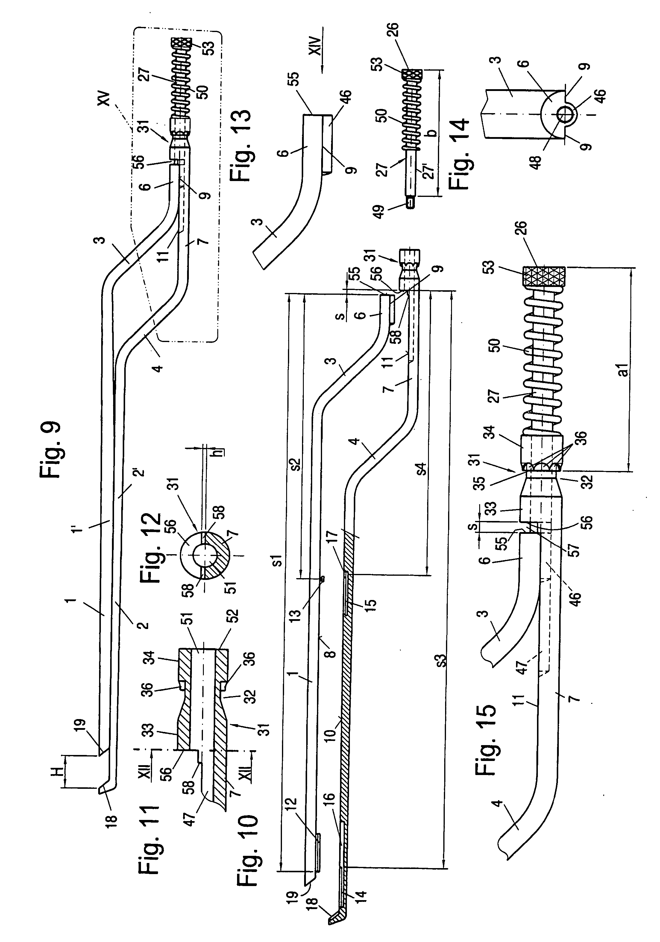
[0039] Referring to the drawings in particular, The instrument shown in the drawings is a laminectomy punch with two punch shafts, namely, a punching slide 1 and a punching bar 2, both of which are uniformly bent at right angles and thus have sections 3 and 4, which extend obliquely in relation to the straight shaft sections 1′ and 2′ and whose rear sections 6 and 7 lie in one another in a slidingly displaceable manner.

[0040] It is achieved due to the two oblique sections 3 and 4 of the punching slide 1 and of the punching bar 2 that the two straight sections 1′ and 2′ of these punch shafts extend radially offset from the axis 5 of the mounting part 20 but in parallel thereto.

[0041] While the obliquely extending sections 3 and 4 may have any desired cross-sectional shape, the sections 1′ and 2′ as well as 6 and 7, which lie one on top of another, are provided with flat sliding surfaces 8 and 9 or guiding surfaces 10 and 11 on the sides facing each other (FIG. 10). In the area of t...


PUM


Abstract

A surgical punching instrument with a fixed handle (21) is attached to a tubular guide part (20). An actuating lever (23) is mounted on the fixed handle (21) in a pivotingly movable manner and is in connection with a plunger (27) via a short lever arm (24). This plunger is in turn connected to a punching slide (1) and is mounted for actuating same against the action of a compression spring in an axially movable manner in a rearward mounting part (31) of a punching bar (2), which is guided rotatably by an at least partially cylindrical guide section (33, 34) and lockably in different rotated positions in the guide part (20). The punching bar is in contact in the guide part (20) with an axial stop acting in the direction of actuation with a ring shoulder (35) and it is locked in an axially detachable manner. The axial stop, with which the ring shoulder (35) is in contact, comprises a spring-loaded locking lever (37), which passes through a guide slot (45) of the guide part (20) radially into a cylindrical cavity (20′) of the guide part (20), in which the guide section (33, 34) of the mounting part (31) of the punching bar (2) is guided.

Description

CROSS REFERENCE TO RELATED APPLICATIONS [0001] This application claims the benefit of priority under 35 U.S.C. § 119 of German Patent Application DE 20 2004 015 990.2 filed Oct. 14, 2004, the entire contents of which are incorporated herein by reference. FIELD OF THE INVENTION [0002] The present invention pertains to a surgical punching instrument with a fixed handle attached to a tubular guide part and with an actuating lever, which is mounted thereon in a pivotingly movable manner and which is in connection via a short lever arm with a plunger, which is in turn connected to a punching slide and is mounted for actuating same against the action of a compression spring in an axially movable manner in a rearward mounting part of a punching bar, which is guided rotatably by means of an at least partially cylindrical guide section and lockably in different rotated positions in the guide part, the punching bar being in contact in the guide part with an axial stop acting in the direction ...

Claims


Application Information

Patent Timeline
Patent Type & Authority Applications(United States)
IPC IPC(8): A61B17/32A61B17/00A61B17/28A61B17/92A61B19/00
CPCA61B17/1611A61B2017/0046A61B2017/292A61B2017/925A61B2019/4868A61B2090/0813
Inventor WENZLER, JORG
Owner JORG WENZLER MEDIZINTECHN
Why Eureka
Try Eureka