Apparatus, system, and method for pivotal installation and removal of an expansion card

Inactive Publication Date: 2006-04-27
IBM CORP
View PDF15 Cites 9 Cited by
  • Summary
  • Abstract
  • Description
  • Claims
  • Application Information

AI Technical Summary

Benefits of technology

[0012] The apparatus, in one embodiment, is configured to provide a means for pivotal mating of a blind-swapped expansion card. A cassette receives an expansion card and is configured to be inserted into a chassis having an expansion card docket for receiving the contact portion of the expansion card. The cassette facilitates pivotal mating of the contact portion with the expansion card docket. In one embodiment, the cassette is inserted longitudinally into the chassis. A cassette coupler may restrain portions of the cassette against vertical movement upon insertion.
[0013] The cassette may include a front plate and a back plate. To protect the expansion card, the front and back plate may substantially cover front and back surfaces of the expansion card. The front plate may remain substantially fixed vertically when inserted into the chassis. The back plate pivotally secures to the front plate and remains pivotable when inserted into the chassis. The back plate may be pivoted downwardly to mate the contact portion with the expansion card docket after insertion. A handle may secure to the back plate and facilitate gripping by a user to pivot the back plate downwardly.
[0014] The front plate and back plate may be pivotally coupled by a pivot stud connected to the back plate. A pivot stud lock on the front plate may prevent removal of the front plate from the pivot stud. In one embodiment, the pivot stud is inserted into an aperture on the front plate, and the pivot stud lock is slid into place, pinching the pivot stud between the font plate and the lock. Once secured, the back plate may pivot with respect to the front plate. The pivot stud may also provide a groove, or like structure, for engagement with the cassette coupler when the cassette is inserted into the chassis.

Problems solved by technology

In complicated servers, this may require the knowledge of a technician to successfully install an expansion card.
However, inasmuch as only one end of the expansion card is accessible, it is very difficult to apply the downward force necessary to insert the contact portion.
Such forces impose large stresses on the delicate components of the expansion card.
The complexity of these prior systems makes them expensive to manufacture and too complicated to provide a customer replaceable unit (CRU), requiring instead the specialized skill of a manufacturer trained technician in order to install expansion cards.

Method used


Image

  • Apparatus, system, and method for pivotal installation and removal of an expansion card
  • Apparatus, system, and method for pivotal installation and removal of an expansion card
  • Apparatus, system, and method for pivotal installation and removal of an expansion card

Examples


Embodiment Construction

[0040] Reference throughout this specification to “one embodiment,”“an embodiment,” or similar language means that a particular feature, structure, or characteristic described in connection with the embodiment is included in at least one embodiment of the present invention. Thus, appearances of the phrases “in one embodiment,”“in an embodiment,” and similar language throughout this specification may, but do not necessarily, all refer to the same embodiment.

[0041] Furthermore, the described features, advantages, and characteristics of the invention may be combined in any suitable manner in one or more embodiments. One skilled in the relevant art will recognize that the invention can be practiced without one or more of the specific features or advantages of a particular embodiment. In other instances, additional features and advantages may be recognized in certain embodiments that may not be present in all embodiments of the invention.

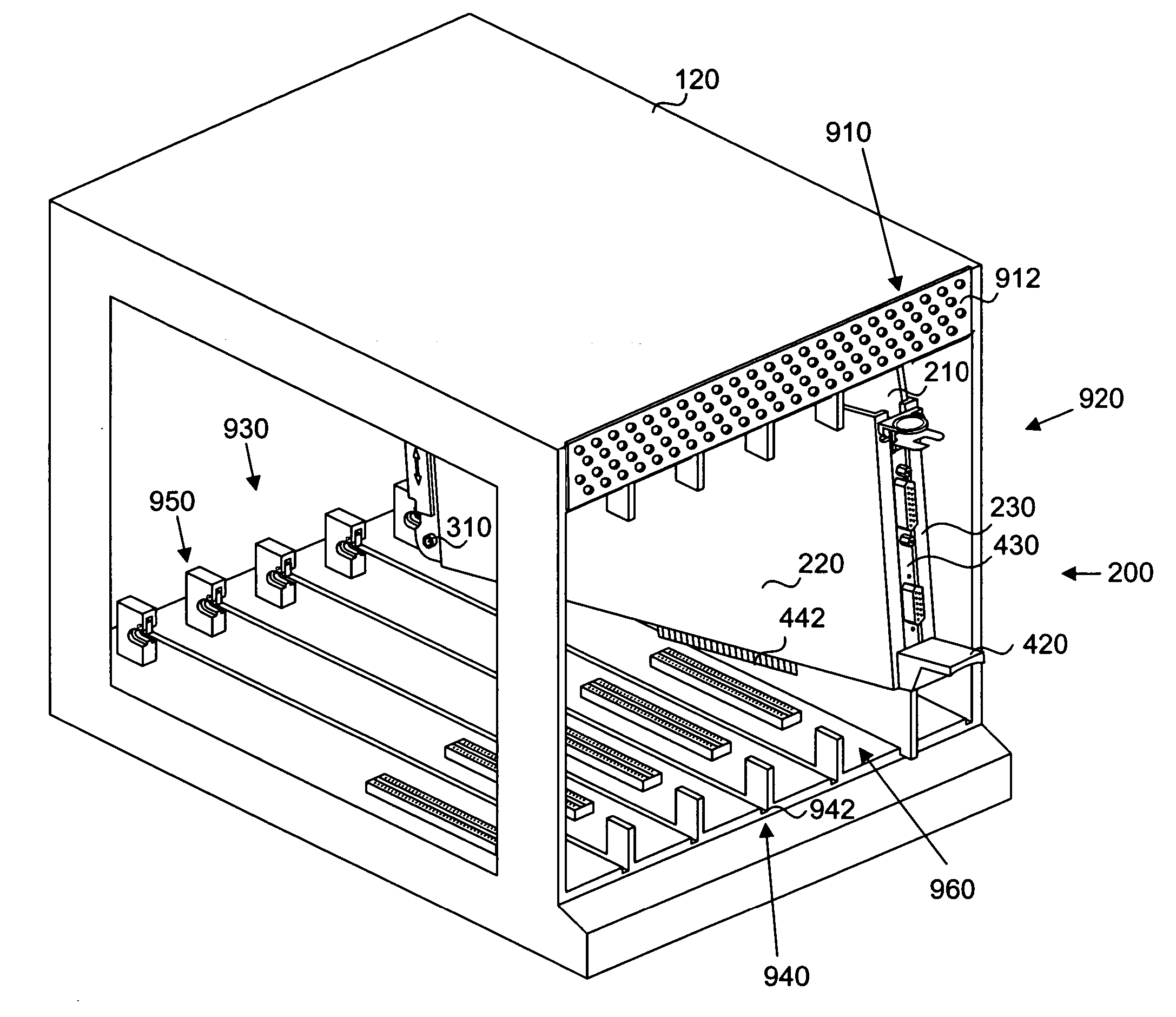
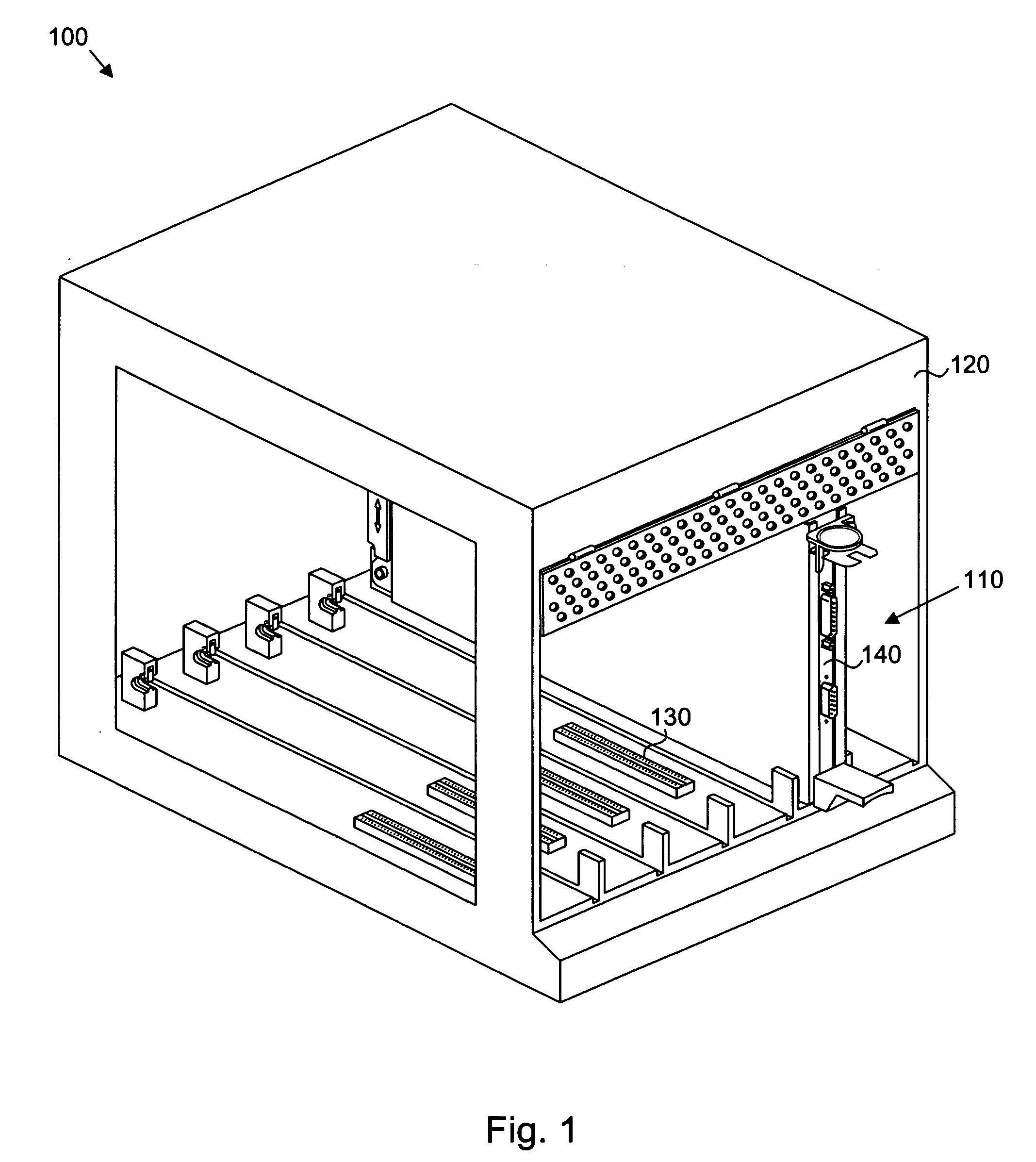
[0042]FIG. 1 illustrates one embodiment of a sys...


PUM

PropertyMeasurementUnit
Forceaaaaaaaaaa
Sizeaaaaaaaaaa
Electrical conductoraaaaaaaaaa

Abstract

A system for installation and removal of an expansion card is disclosed. An expansion card is mounted to a cassette having a front plate and a back plate. The cassette is sized to fit within a chassis. The chassis is provided with a connector that is configured to receive a connection portion of an expansion card. The front plate inserts into the chassis and remains substantially vertically fixed after insertion. The back plate is pivotable with respect to the chassis when inserted. Once inserted, the back plate is pivoted downward to engage the contact portion of the expansion card with the connector. The back plate may be removable from the front plate to fasten expansion cards thereto. Fasteners securing the expansion card to the back plate may be adjustable.

Description

BACKGROUND OF THE INVENTION [0001] 1. Field of the Invention [0002] The invention relates generally to expansion card devices, methods, and systems. Specifically, the invention relates to devices for installing and removing expansion cards without tools. [0003] 2. Description of the Related Art [0004] A typical computer system includes a computer case made of metal or plastic storing a motherboard controlling the operation of the computer and various secondary storage devices, such as hard drives, connected to the motherboard. Additional “daughterboards” or expansion cards may be connected to the motherboard, or a dedicated circuit board connected to the motherboard, to provide additional functionality. The computer case typically includes an opening exposing a portion of the expansion cards, referred to as a tail stock, to receive cables connecting the cards to peripheral devices or other computers. [0005] Typical expansion cards include video cards for rendering video data to be t...

Claims


Application Information

Patent Timeline
IPC IPC(8): B23P19/00
CPCG06F1/185Y10T29/49895Y10T29/49822
Inventor KERRIGAN, BRIAN MICHAELMILLER, MICHAEL SVENSYED, FARRUKH SHAHZAD
Owner IBM CORP
Why Eureka
Try Eureka