

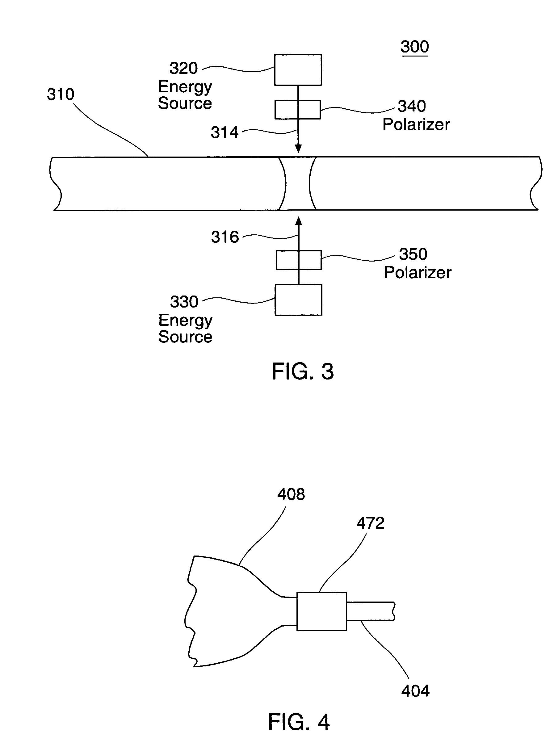
Method of applying one or more electromagnetic beams to form a fusion bond on a workpiece such as a medical device
a technology of electromagnetic beams and workpieces, applied in the field of medical devices, can solve the problems of leakage of inflation fluid, rapid loss of pressure and balloon deflation, and inability to achieve the desired pressur
- Summary
- Abstract
- Description
- Claims
- Application Information
AI Technical Summary
Benefits of technology
Problems solved by technology
Method used
Image

Examples
Embodiment Construction
[0049] While this invention may be embodied in many different forms, there are described in detail herein specific embodiments of the invention. This description is an exemplification of the principles of the invention and is not intended to limit the invention to the particular embodiments illustrated.
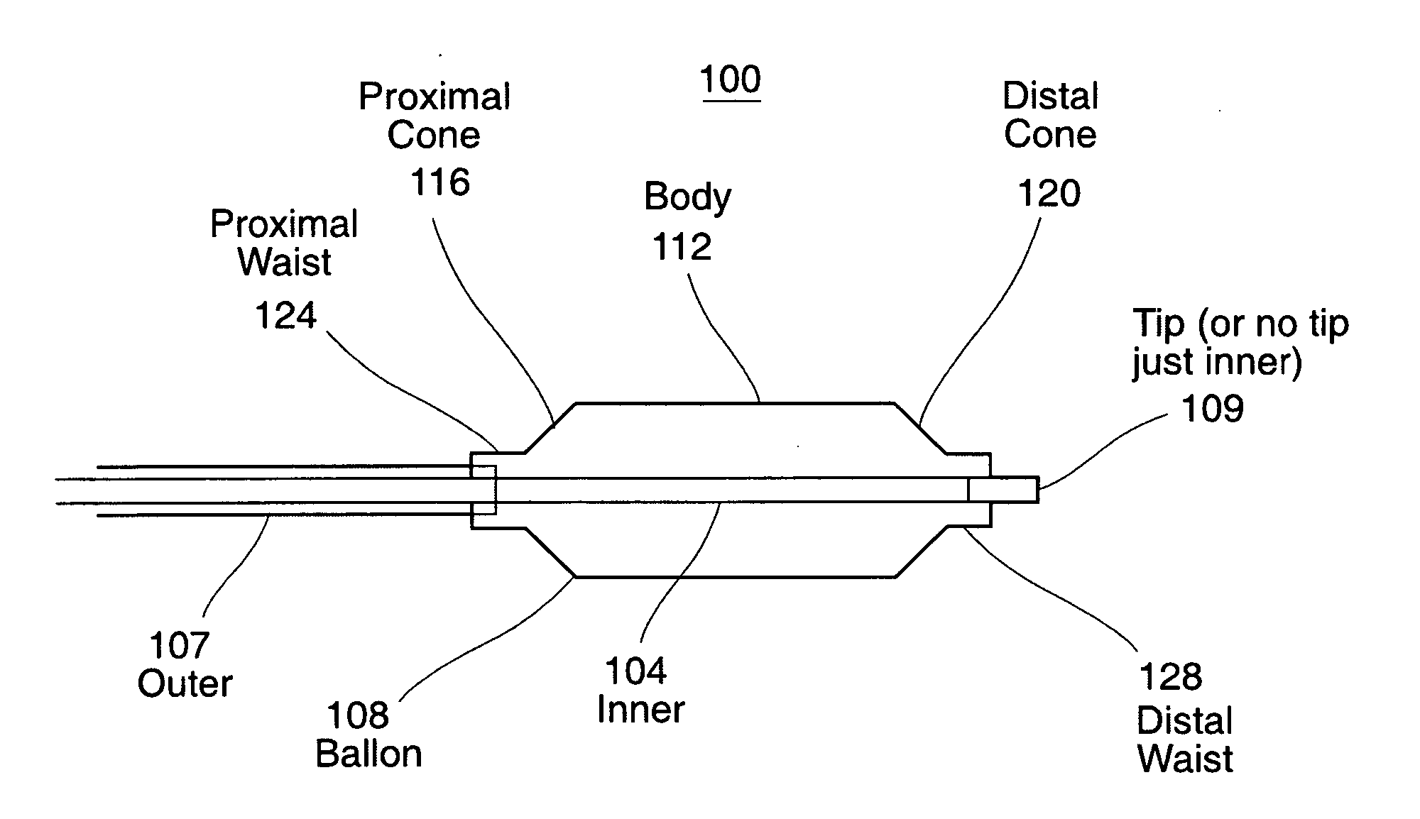
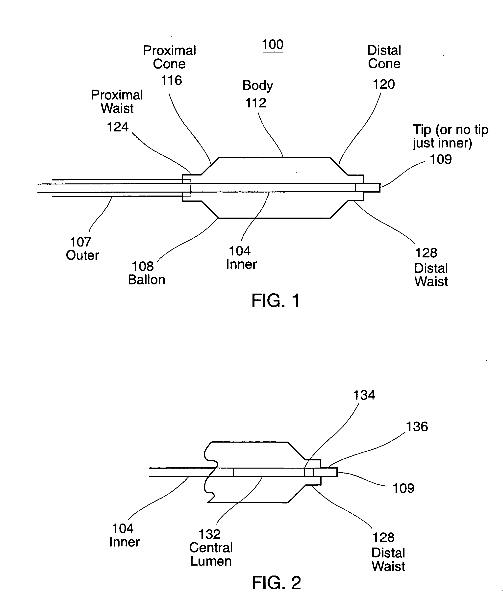
[0050] The present invention is directed to methods and apparatuses for effectively welding or bonding workpiece components such as polymeric materials together, and in particular for bonding components of medical devices, such as catheters. Additionally an aspect of the present invention may be used to bond polymeric materials to non-polymeric materials such as metals, for example, stainless steel as well as other non-polymeric materials such as ceramics and glasses. In particular, the present invention can advantageously provide the ability to bond tubular components of polymeric materials together as are usable for making up components of medical catheters of all types.
[0051] In ...
PUM
| Property | Measurement | Unit |
|---|---|---|
| wavelength | aaaaa | aaaaa |
| length | aaaaa | aaaaa |
| length | aaaaa | aaaaa |
Abstract
Description
Claims
Application Information