Image forming device

a technology of forming device and image, which is applied in the direction of instruments, electrographic process equipment, optics, etc., to achieve the effect of high accuracy

Inactive Publication Date: 2006-04-27
FUJIFILM BUSINESS INNOVATION CORP
View PDF2 Cites 6 Cited by
  • Summary
  • Abstract
  • Description
  • Claims
  • Application Information

AI Technical Summary

Benefits of technology

[0009] The present invention was developed in order to overcome the above-described drawback, and an object of the present invention provides an image forming device which can correct positional offset among images with high accuracy.

Problems solved by technology

However, until the pattern images are sensed, and the correction amounts are computed on the basis of the sensed results, and exposure, in which the electrostatic latent image formation start timings are corrected on the basis of the correction amounts, is actually carried out, there is the problem that positional offset arises due to elongation of the continuous sheet of paper, fluctuations in the conveying speed of the continuous sheet of paper, and the like.

Method used


Image

  • Image forming device
  • Image forming device
  • Image forming device

Examples


Embodiment Construction

[0017] An embodiment of the present invention will be described hereinafter with reference to the drawings.

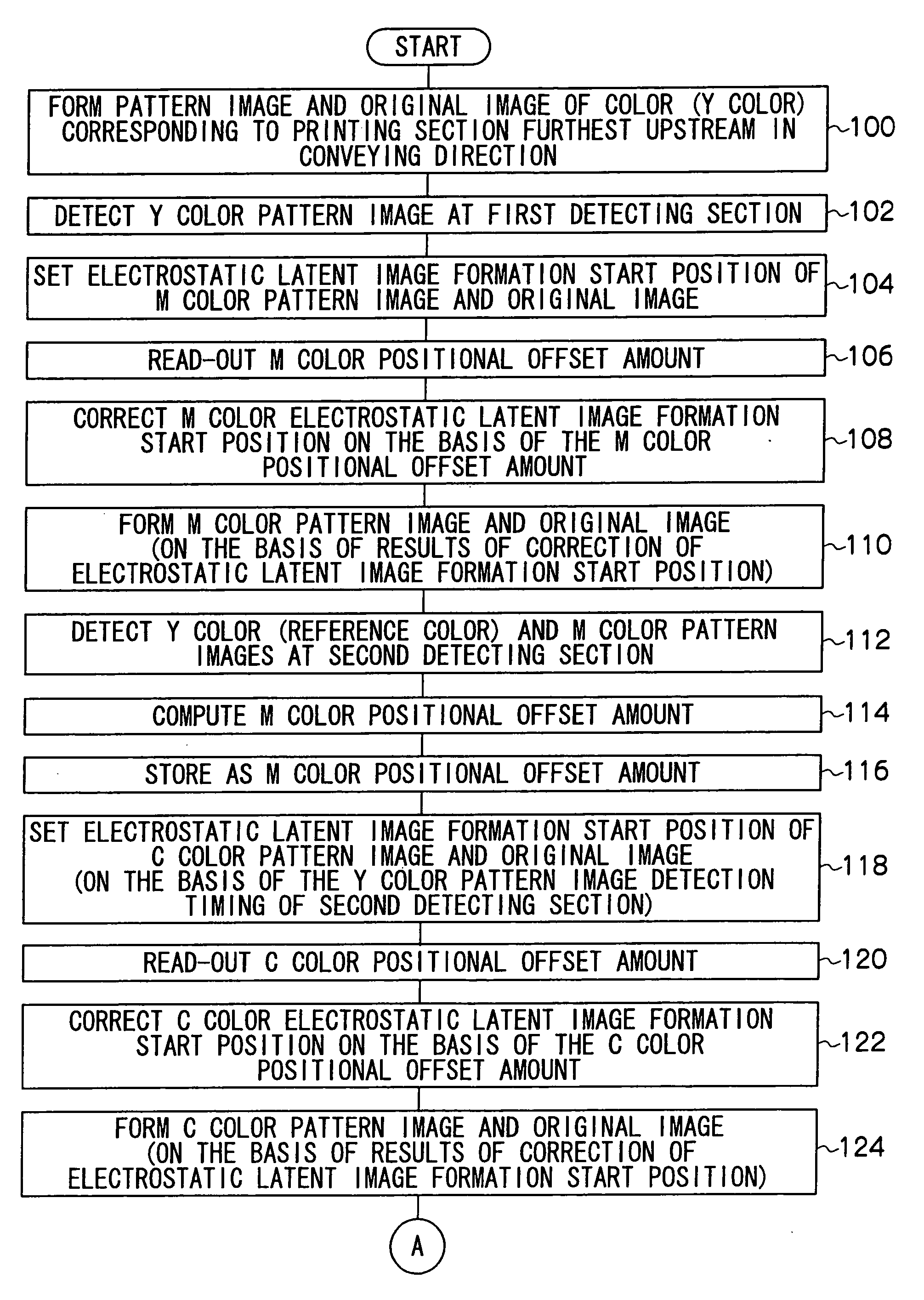
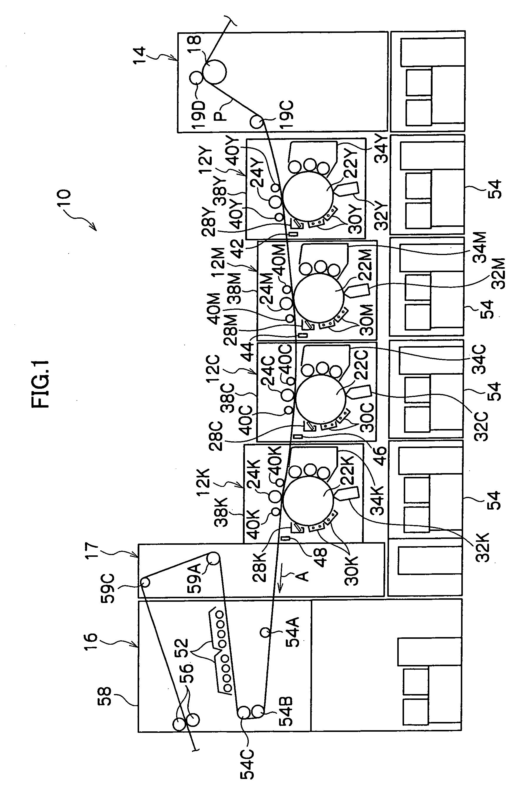
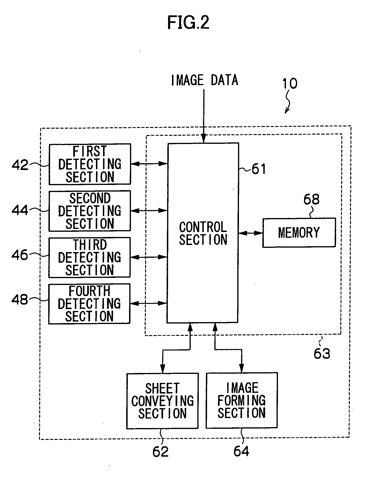
[0018] As shown in FIG. 1, an image forming device 10 has four image printing units which successively transfer color toner images of yellow (Y), magenta (M), cyan (C), and black (K) onto a continuous sheet of paper P, i.e., a printing section 12Y, a printing section 12M, a printing section 12C, and a printing section 12K. The printing section 12Y, the printing section 12M, the printing section 12C, and the printing section 12K are lined-up in that order from the upstream side toward the downstream side in the conveying direction of the continuous sheet of paper P. A sheet supplying section 14, which conveys the continuous sheet of paper P to the printing section 12Y, the printing section 12M, the printing section 12C, and the printing section 12K, is provided at the conveying direction upstream side of the printing section 12Y. A fixing section 16 and a sheet discharging sect...


PUM


Abstract

Electrostatic latent images of a pattern image and an original image are formed on each of a plurality of image carriers. Each image carrier is provided with a developing unit and a transfer unit, and images of a reference color and colors other than the reference color are formed on a continuous sheet of paper. Detectors that detect the pattern images on the continuous sheet are disposed at conveying direction downstream sides of image carriers, and positional offset amounts of the pattern images of the colors other than the reference color are computed. On the basis of a detection of the pattern image of the reference color, a start position of electrostatic latent image formation at each image carrier is determined. Further, the start position is corrected on the basis of a positional offset amount computed at a time of transferring a preceding pattern image.

Description

CROSS-REFERENCE TO RELATED APPLICATION [0001] This application claims priority under 35 USC 119 from Japanese Patent Application No. 2004-311087, the disclosure of which is incorporated by reference herein. BACKGROUND OF THE INVENTION [0002] 1. Field of the Invention [0003] The present invention relates to an image forming device, and in particular, to an image forming device which forms images on a continuous sheet of paper or an uncut sheet of paper. [0004] 2. Description of the Related Art [0005] As a conventional image forming device, there is known a tandem-type image forming device in which toner images of plural colors such as yellow, magenta, cyan, black, and the like are formed respectively on plural image carriers which are lined-up along the conveying path of a continuous sheet of paper, and the color toner images formed on the respective image carriers are transferred, in a superposed manner, onto a continuous sheet of paper which is being conveyed, so as to form an imag...

Claims


Application Information

Patent Timeline
Patent Type & Authority Applications(United States)
IPC IPC(8): G03G15/01
CPCG03G2215/0119G03G15/0194G03G2215/0161
Inventor AIKAWA, KIYOFUMI
Owner FUJIFILM BUSINESS INNOVATION CORP
Why Eureka
Try Eureka