Rasp attachment for a motor-driven surgical hand-held device

Active Publication Date: 2006-04-27
NOLDE MARTIN
View PDF17 Cites 74 Cited by
  • Summary
  • Abstract
  • Description
  • Claims
  • Application Information

AI Technical Summary

Benefits of technology

[0018] The present invention is based on the finding that a surgeon may respectively take off or model solid tissue, for example a bone, a lot more easily if he can, in this process, exclusively concentrate on the arrangement and alignment of the rasp in relation to the tissue to be modeled, to the contact pressure and feeling the interaction between the rasp and the tissue, and does not simultaneously have to apply force and energy and pay attention to the evenness of his manual rasp movements. The present invention has in this connection the advantage that the surgeon is able to take off material with less effort and considerably more sensitively, evenly and smoothly than when using a conventional hand rasp.
[0019] According to the present invention, the actual rasp operation is performed by the motor-driven surgical hand-held device, the intrinsic characteristic of which is that it performs the reciprocating material take-off movement of the rasp or filing attachment, respectively, almost completely uniformly in a cinematic and dynamic respect. The surgeon can concentrate on accurately determining the location of the material take-off by the arrangement and alignment of the rasp attachment in relation to the tissue to be modeled, setting the take-off rate by the contact pressure of the rasp attachment or from its rasp area to the surface to be removed, respectively, observing the interaction of the rasp attachment with the surface to be removed and shifting the location of the material take-off as continuously as possible if applicable by a slow and uniform swivel or translation movement of the hand-piece in order to, for example, prevent the formation of steps. The observation of the interaction of the rasp attachment with the surface to be treated mainly includes an observation of the friction force between the rasp area and the surface to be removed. Further, it includes an observation of the reaction on the motor-driven hand-piece which, for example, influences the frequency of the reciprocating movement or a noticeable shaking of the hand-piece. Apart from that, the surgeon may, for example, feel steps and edges on the surface to be removed, for example, via the rasp attachment and the hand-piece. All of this enables an easier, fatigue-reduced and thus more concentrated, precise, tissue-conserving, faster and thus more time-saving operation.
[0020] The rasp attachment is curved in one or two directions at least in the rasp area, wherein the rasp area may be both convex and concave. A curved rasp area has the advantage that curved surfaces may easily be modeled and that the risk of a step formation at a surface to be taken off is reduc

Problems solved by technology

This narrow pass situation mainly leads to chronic movement and stress-dependent pain in the shoulder area in the middle phase of life.
Frequently, the chronic, mechanical irritation also leads to progressing damage of a tendon cuff located below the akromion, the r

Method used


Image

  • Rasp attachment for a motor-driven surgical hand-held device
  • Rasp attachment for a motor-driven surgical hand-held device
  • Rasp attachment for a motor-driven surgical hand-held device

Examples


Example

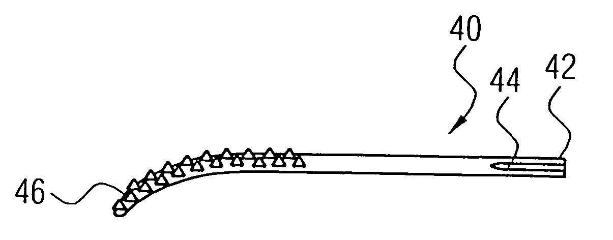
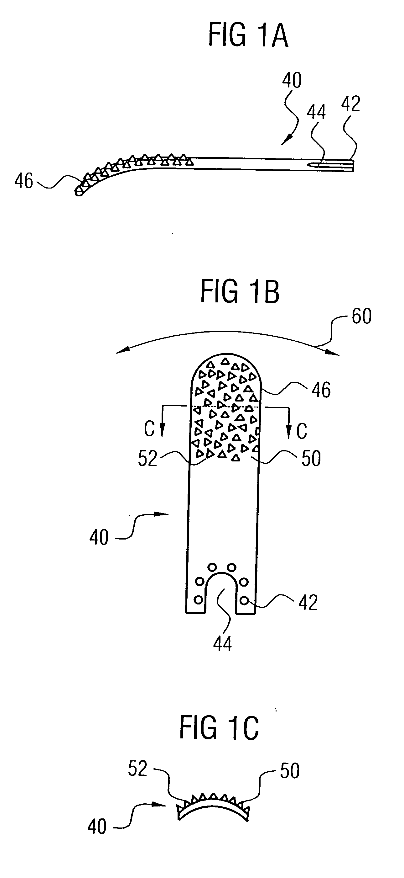
[0030]FIGS. 1A, 1B, 1C show a rasp attachment 40 according to a preferred embodiment of the present invention from three different perspectives. The rasp attachment 40 has approximately the shape of a slightly curved, oblong small plate or metal sheet strip, respectively. FIG. 1A shows the rasp attachment 40 in a side view or from a direction perpendicular to the direction in which the rasp attachment has its greatest extension, respectively, and approximately parallel to the direction in which the rasp attachment 40 has its second largest extension. FIG. 1B shows the rasp attachment 40 in a view from above, in a view from the side at which the rasp area is arranged, and in a view from a direction in which the rasp attachment has its smallest extension, respectively. FIG. 1C shows an illustration of a section through the rasp attachment 40 along the line C-C in FIG. 1B.

[0031] It may be seen that the rasp attachment 40 approximately comprises the shape of an oblong, rectangular shee...


PUM


Abstract

A rasp attachment for a motor-driven surgical hand-piece includes a mounting means for mounting the rasp attachment to the motor-driven surgical hand-piece and a rasp area which is implemented to take off material from a surface in a reciprocating movement of the rasp attachment caused by the motor-driven surgical hand-piece. the rasp to is curved and elastically deformable at least in the rasp area.

Description

CROSS-REFERENCE TO RELATED APPLICATIONS [0001] This application is a continuation of co-pending International Application No. PCT / EP2004 / 001863, filed Feb. 25, 2004, which designated the United States and was not published in English.BACKGROUND OF THE INVENTION [0002] 1. Field of the Invention [0003] The present invention relates to a rasp attachment for a motor-driven hand-held device for taking off bones or other solid tissue. [0004] 2. Description of the Related Art [0005] In numerous surgical operations bone substance is taken off by filing, rasping, planing or milling in order to model bone surfaces. This is, for example, required to remove a narrow pass situation, prepare the insertion of an implant or post-process surface structures which resulted from a previous coarser processing step. Subsequently, an example from shoulder surgery is described. [0006] At the human shoulder, an anatomic variant of the akromion frequently leads to a bone narrow pass situation which is referr...

Claims


Application Information

Patent Timeline
IPC IPC(8): A61B17/16
CPCA61B17/1659A61B17/1682A61B17/1684A61B17/1686A61B2017/320028
Inventor NOLDE, MARTIN
Owner NOLDE MARTIN
Why Eureka
Try Eureka