Centrifugal oil separator

a centrifugal oil separator and centrifugal technology, applied in centrifuges, auxillary pretreatment, separation processes, etc., can solve the problem of substantial pressure drop across the oil separator, and achieve the effect of minimizing the pressure drop

Inactive Publication Date: 2006-05-04
MANN HUMMEL GMBH
View PDF10 Cites 38 Cited by
  • Summary
  • Abstract
  • Description
  • Claims
  • Application Information

AI Technical Summary

Benefits of technology

[0005] The object of the present invention is to provide a centrifugal separator in which the pressure drop is minimized.

Problems solved by technology

In such a case, it is unavoidable that a substantial pressure drop will occur across the oil separator.

Method used


Image

  • Centrifugal oil separator
  • Centrifugal oil separator
  • Centrifugal oil separator

Examples


Embodiment Construction

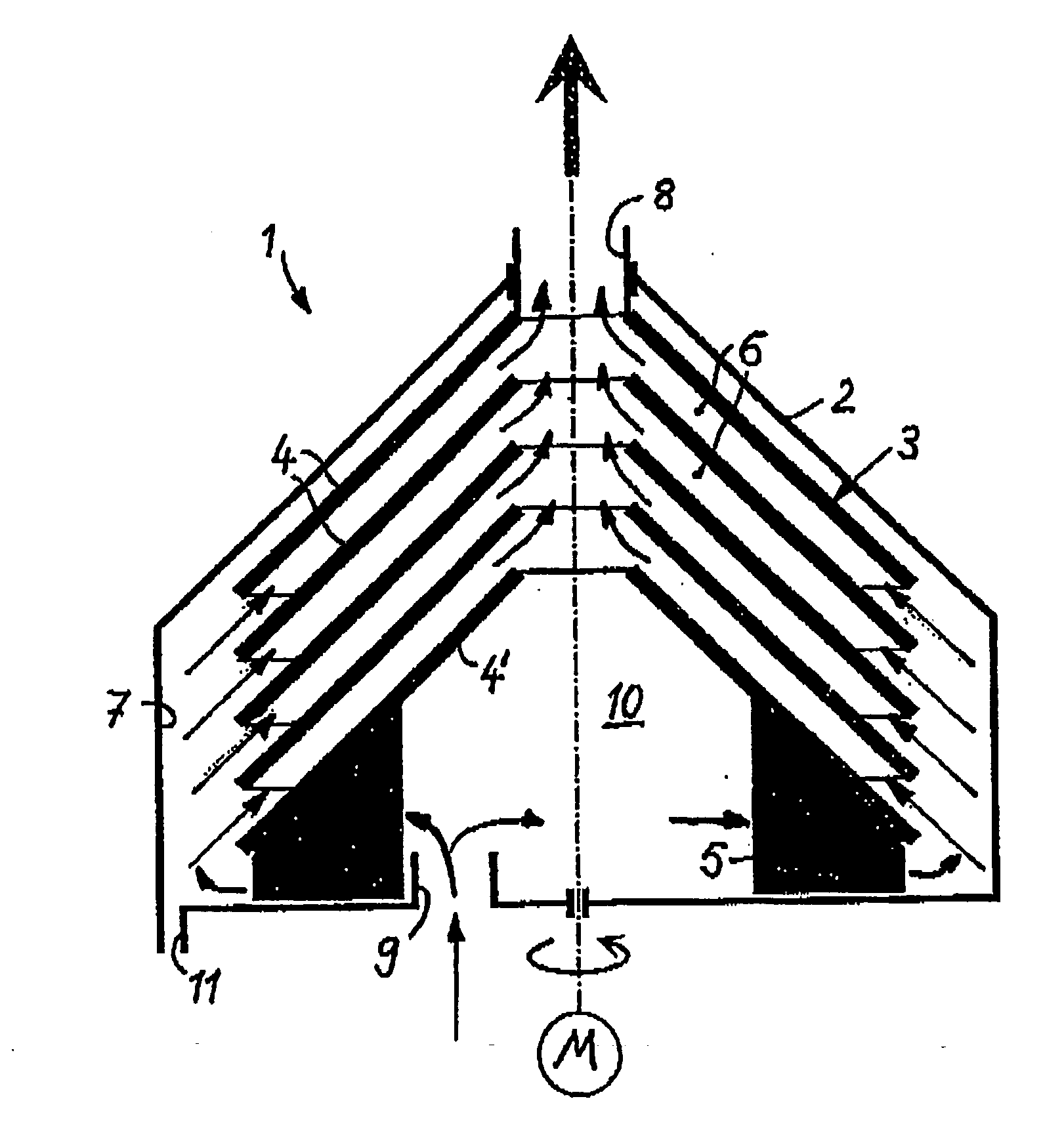
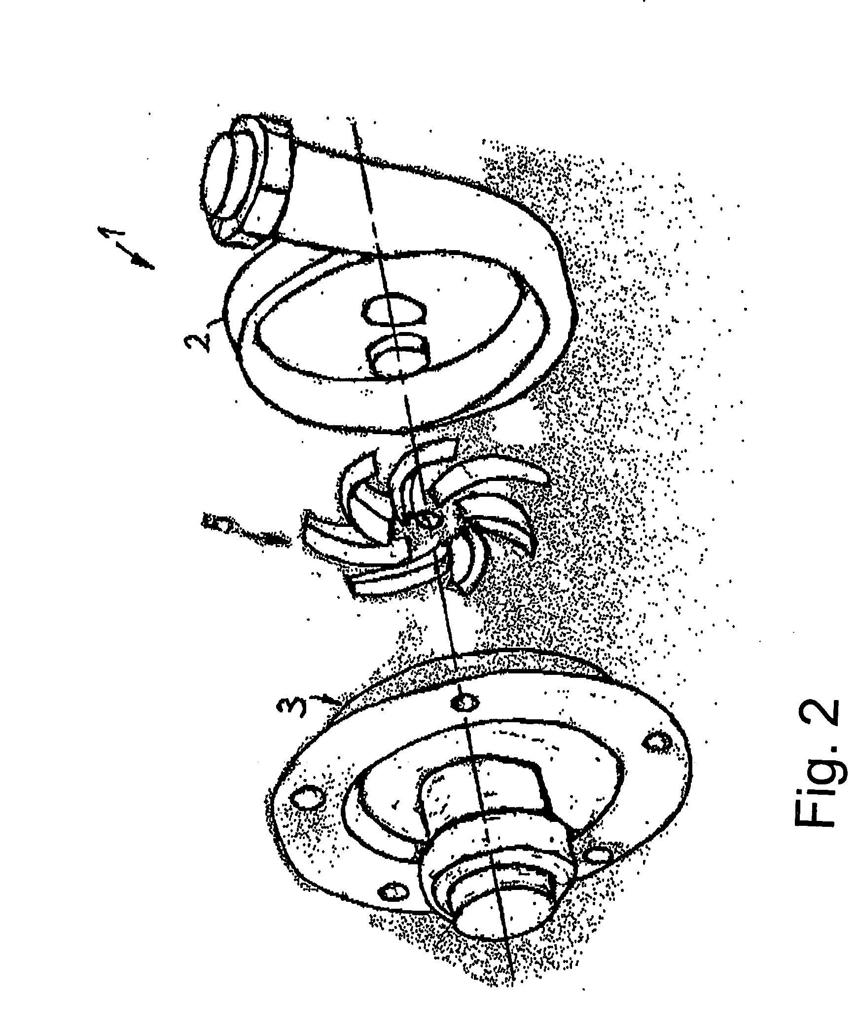
[0014] The centrifugal oil separator 1 shown in FIG. 1 comprises a plate separator 3 which is rotatably mounted in the housing 2 and can be driven by a motor M. The plate separator 3 comprises a plurality of substantially conical plates 4 stacked one above the other and arranged with a distance between them, thus forming flow paths 6 between the plates. The plate separator 3 is surrounded radially by an intake space 7 which is formed between a cylindrical inside wall of the housing 2 and the radial outside of the plate separator. The plate separator 3 has oncoming flow from the outside radially through the oncoming flow space 7, such that the gas to be vented flows radially inwardly along the flow path 6 between the neighboring plates 4 as indicated in the direction of the arrows and is discharged axially as cleaned gas and exhausted from the housing 2 through an axially extending central discharge channel. Because of the conical shape of the plates 4, the flow paths 6 between adjac...


PUM

PropertyMeasurementUnit
distanceaaaaaaaaaa
centrifugal forcesaaaaaaaaaa
pressureaaaaaaaaaa

Abstract

A centrifugal oil separator which includes a disk separator disposed in a housing and has a plurality of spaced disks between which paths of flow for a gas to be cleaned are provided. The paths of flow connect an intake space located at the radial exterior of the disk separator with an inner, axial discharge channel. The intake space is supplied with pressurized gas via a rotation element that is configured as a compressor wheel and that is disposed in the area of an axial end face of the disk separator.

Description

CROSS REFERENCE TO RELATED APPLICATIONS [0001] This application is a continuation of international patent application no. PCT / EP2004 / 050010, filed Jan. 9, 2004, designating the United States of America and published in German as WO 2004 / 063538 on Jul. 29, 2004, the entire disclosure of which is incorporated herein by reference. Priority is claimed based on Federal Republic of Germany patent application no. DE 103 00 729.6, filed Jan. 11, 2003.BACKGROUND OF THE INVENTION [0002] This invention relates to a centrifugal oil separator with a housing enclosing a plate separator comprising a plurality of spaced plates forming between them flow paths for a gas to be cleaned. [0003] Published U.S. Patent Application No. US 2003 / 0178014 A1 (=DE 100 44 615) discloses a centrifugal oil separator for separating entrained oil from gases vented from the crankcase of an internal combustion engine. The centrifugal oil separator comprises a rotatably mounted and drivable plate separator in a separato...

Claims


Application Information

Patent Timeline
Patent Type & Authority Applications(United States)
IPC IPC(8): B01D45/00F01M13/04
CPCF01M13/04F01M2013/0422B04B5/12B04B2005/125
Inventor TRAUTMAN, PIUSDURST, MICHAEL
Owner MANN HUMMEL GMBH
Why Eureka
Try Eureka