
Safety net system

a safety net and net system technology, applied in the field of safety net systems, can solve the problems of delayed work progress, difficulty in moving between floors and ensuring the position of the net, and the crew member's inability to adjust the height of the net, so as to achieve quick and easy securement to the building

Inactive Publication Date: 2006-05-04
REXROAD JOHN
View PDF12 Cites 32 Cited by
  • Summary
  • Abstract
  • Description
  • Claims
  • Application Information

AI Technical Summary

Benefits of technology

[0011] It is a further object of the present invention to provide a safety net system that is easily secured when stationary.
[0012] It is a further object of the present invention to provide a safety net system that can be folded up against the building for cleaning or in inclement weather conditions.
[0013] It is a further object of the present invention to provide a safety net system that can be easily and quickly moved to provide the optimal protection for the crew members.
[0015] It is a further object of the present invention to provide a safety net system that quickly and easily secures to the building.
[0016] It is a further object of the present invention to provide a safety net system that can move between more than one building floor at a time and only requires a higher and lower attachment point.

Problems solved by technology

This can become very time consuming and inconvenient causing delays in the progress of the work.
Because of the time and effort involved, crew members may not adjust the height of the net as often as necessary to avoid the inconvenience.
However, each of these devices suffers from several disadvantages.
First, the devices are difficult to move between floors and secure into position.
They require a multi step process that involves many parts, and the installation process makes it difficult to change the position of the safety net assembly.
Moving the prior art safety net systems each time the crew moves one floor higher or lower is difficult and requires a great deal of time and energy.
The prior art devices are complicated and require a time consuming and inconvenient process.
Second, the prior art devices do not automatically raise and lower the safety net assembly.
The prior art devices require the safety net assembly to be manually raised or lowered when changing positions creating an increased risk for the crew members.
Presently, there is no safety net system that is easy to automatically adjust and secure between floors of a building or can move between more than one building floor at a time.

Method used


Image

  • Safety net system
  • Safety net system
  • Safety net system

Examples


Embodiment Construction

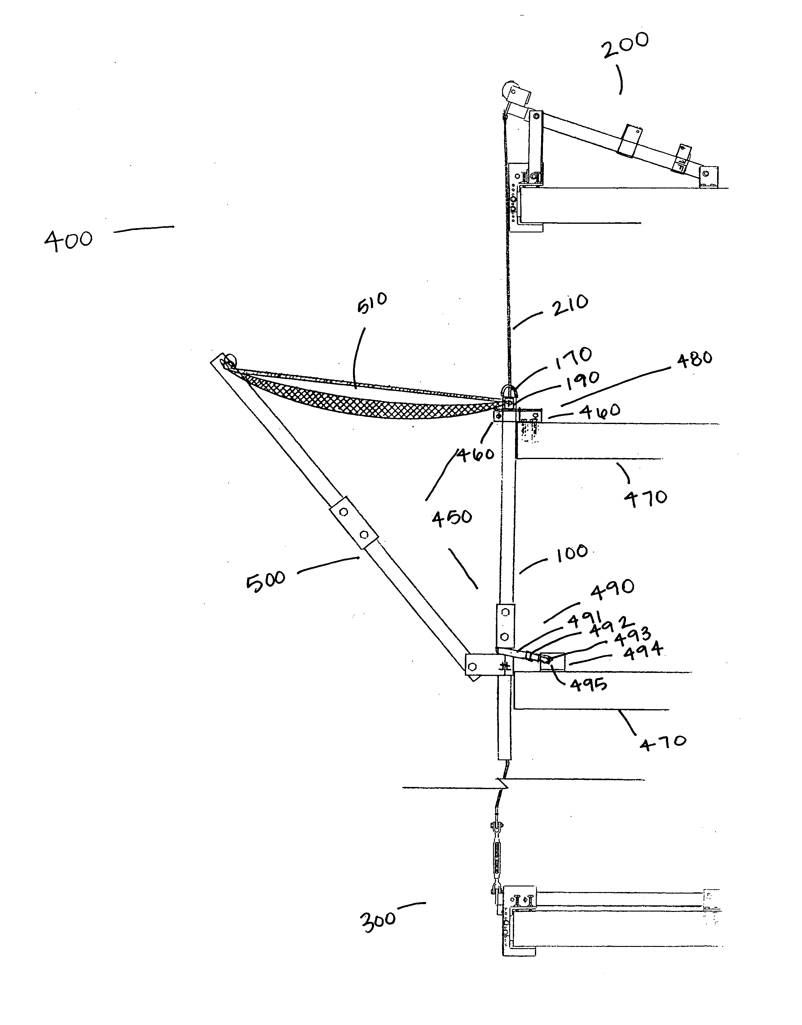
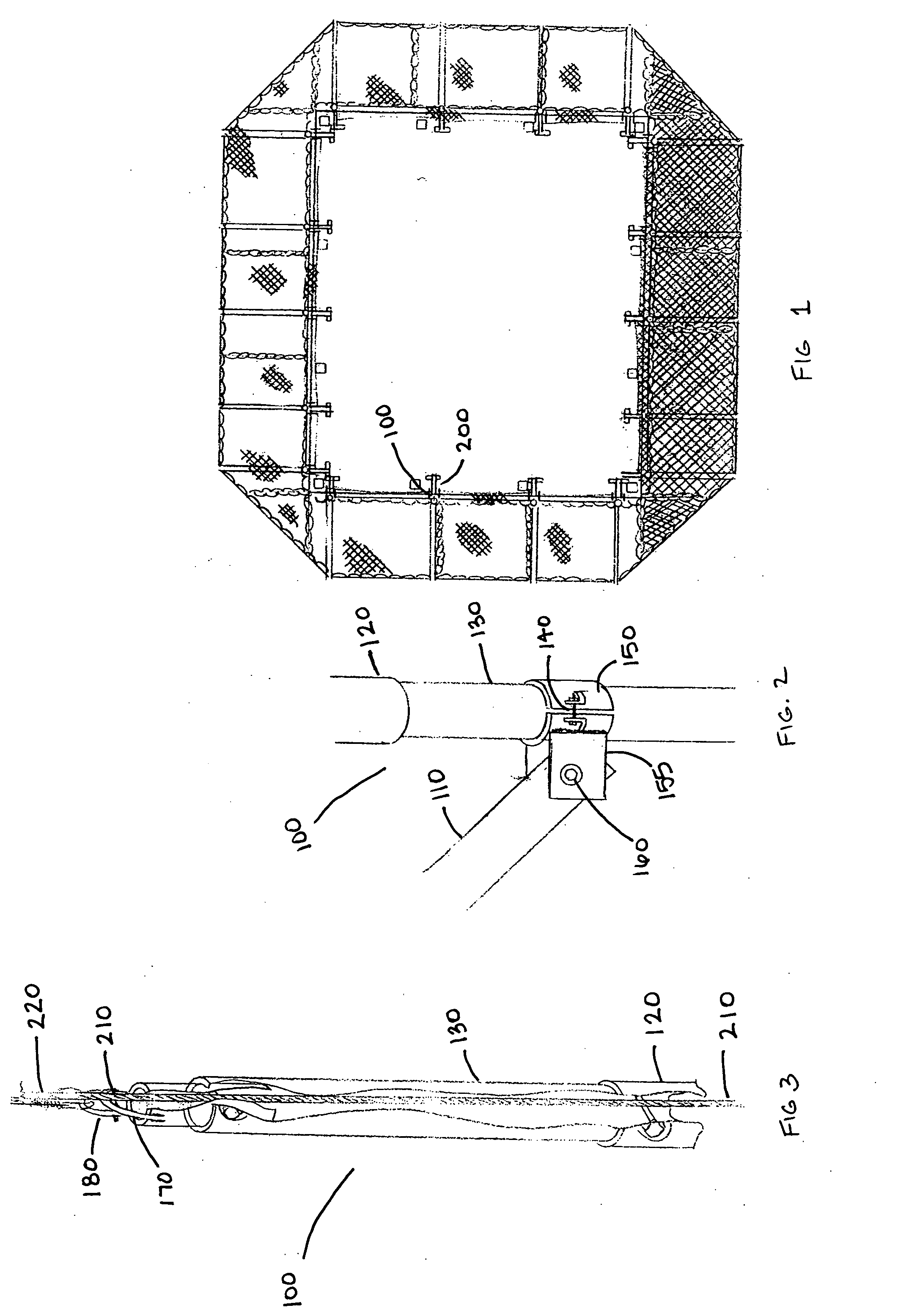
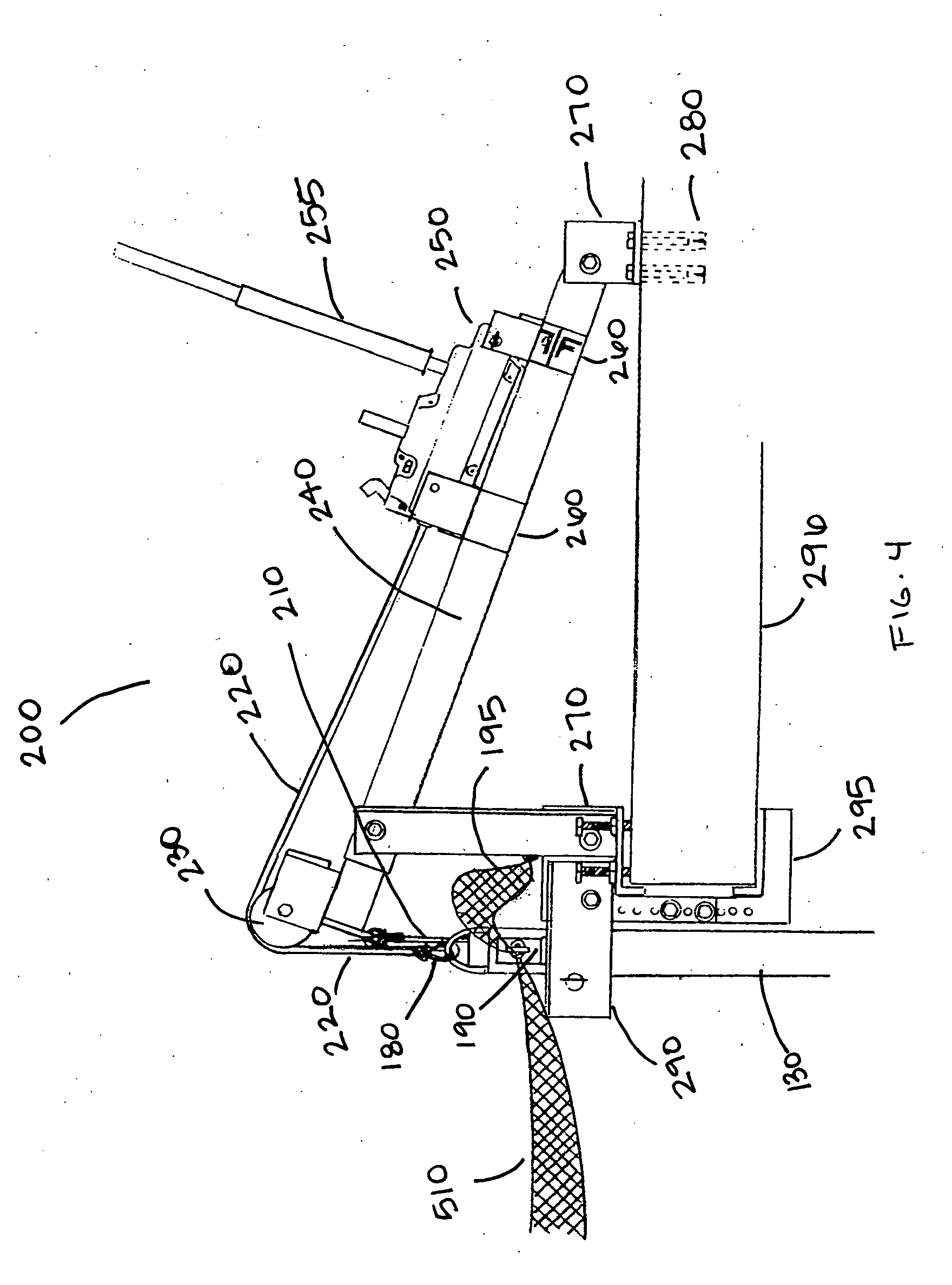
[0036] As shown in FIG. 13, the preferred embodiment of the safety net system 400 generally includes a lifting mechanism 200, a net support assembly 500, an anchoring mechanism 450, and a lower plate assembly 300. These components work together to automatically raise and lower a safety net system 400 attached around the perimeter of a building as shown in FIG. 1.

[0037] As shown in FIGS. 2 and 3, the sliding arm 100 of the net support assembly 500 consists of two sections for easy shipping. In an alternate embodiment, the sliding arm 100 consists of one section. FIG. 3 shows the section of the sliding arm 100 that is attached to the lifting mechanism 200 and the safety net 510. This section of the sliding arm 100 includes a coupler 120, a vertical support 130, and a lifting loop 170. The vertical support 130 is the component of the sliding arm 100 that may move up and down the slide cable 210. The slide cable 210 runs through the vertical support 130 and keeps the net support assemb...


PUM


Abstract

The invention is a safety net system that protects crew members working on high-rise buildings. The safety net system easily adjusts between floors of a high-rise building. The safety net system includes a net support assembly, a lifting mechanism, an anchoring mechanism, and a lower plate assembly. The lifting mechanism is coupled to the net support assembly. When the lifting mechanism is activated, the net support assembly is raised or lowered to the building floor where crew members are working. The anchoring mechanism and the lower plate assembly secure the net support assembly against the building when it is in place. Among other things, the safety net system allows crew members to work on high-rise buildings without the risk of being injured by a fall or dropped objects.

Description

FIELD OF THE INVENTION [0001] The present invention relates generally to an apparatus used for maintaining a safe work environment, more particularly, to an apparatus that comprises a safety net system that maintains a safe work area for crews working on high-rise buildings both on the ground and in the air. Specifically, the present invention utilizes a lifting mechanism that allows a safety net system to easily be moved between the floors of a building undergoing maintenance or construction. BACKGROUND OF THE INVENTION [0002] A crew maintaining or constructing a high-rise building must deal with many hazards in the work environment. Members of the crew on the ground and in the air must be constantly aware of their surroundings. Crew members on the ground must watch for dropped objects falling from above, and crew members working above ground must be conscious of where they are stepping to avoid a fall. [0003] One way to protect the crew is to install a net that surrounds the perim...

Claims


Application Information

Patent Timeline
IPC IPC(8): A62B1/22
CPCA62B1/22E04G21/3261E04G21/3266
Inventor REXROAD, JOHN
Owner REXROAD JOHN
Learn More