Plasma display panel (PDP)

a technology of display panel and transparent electrode, which is applied in the direction of discharge tube/lamp details, gas-filled discharge tubes, electrodes, etc., can solve the problems of poor discharge characteristics, high roughness of corners, and deterioration of the precision level of shaping the transparent electrode layer, so as to improve the discharge characteristics, improve the level of precision in shaping, and reduce roughness

Inactive Publication Date: 2006-05-04
SAMSUNG SDI CO LTD
View PDF11 Cites 2 Cited by
  • Summary
  • Abstract
  • Description
  • Claims
  • Application Information

AI Technical Summary

Benefits of technology

[0019] The PDP of the present invention can improve the level of precision in shaping the transparent electrode layers by rounding off both corners of each protrusion portion facing the paired protrusion portion, to reduce the roughness due to process variations. Therefore, the PDP of the present invention can improve the discharge characteristics and to prevent display failure and to expand the discharge voltage margin.

Problems solved by technology

However, this complicated shape of the transparent electrode layer causes a problem in that its corners, compared with other line portions, has a high degree of roughness due to an increase in process variations during the patterning of the transparent electrode layer by wet etching or laser etching.
That causes the deterioration of the precision level of shaping the transparent electrode layer, which leads to poor discharge characteristics, such as misdischarge and display failures such as image stains.

Method used


Image

  • Plasma display panel (PDP)
  • Plasma display panel (PDP)
  • Plasma display panel (PDP)

Examples


first embodiment

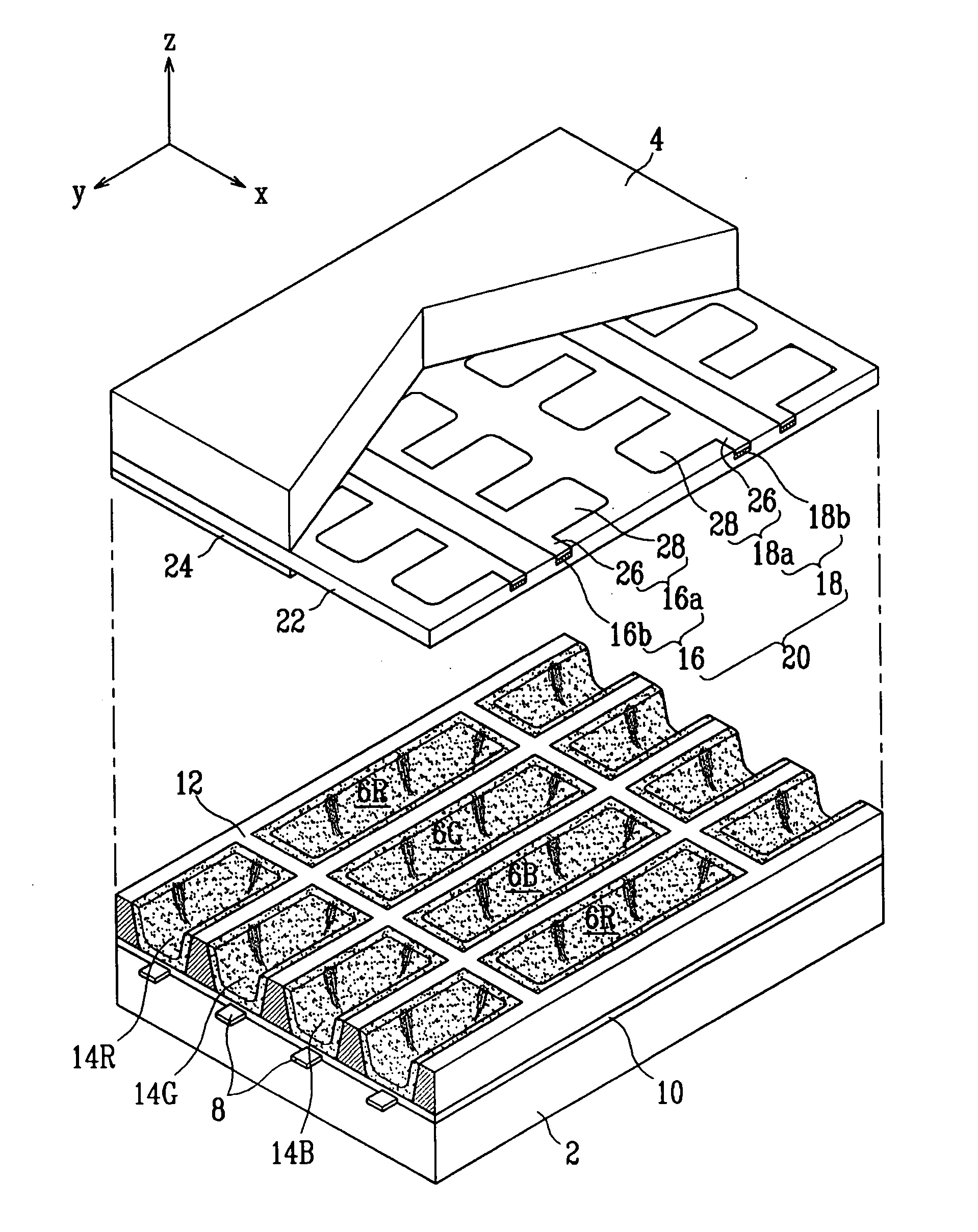
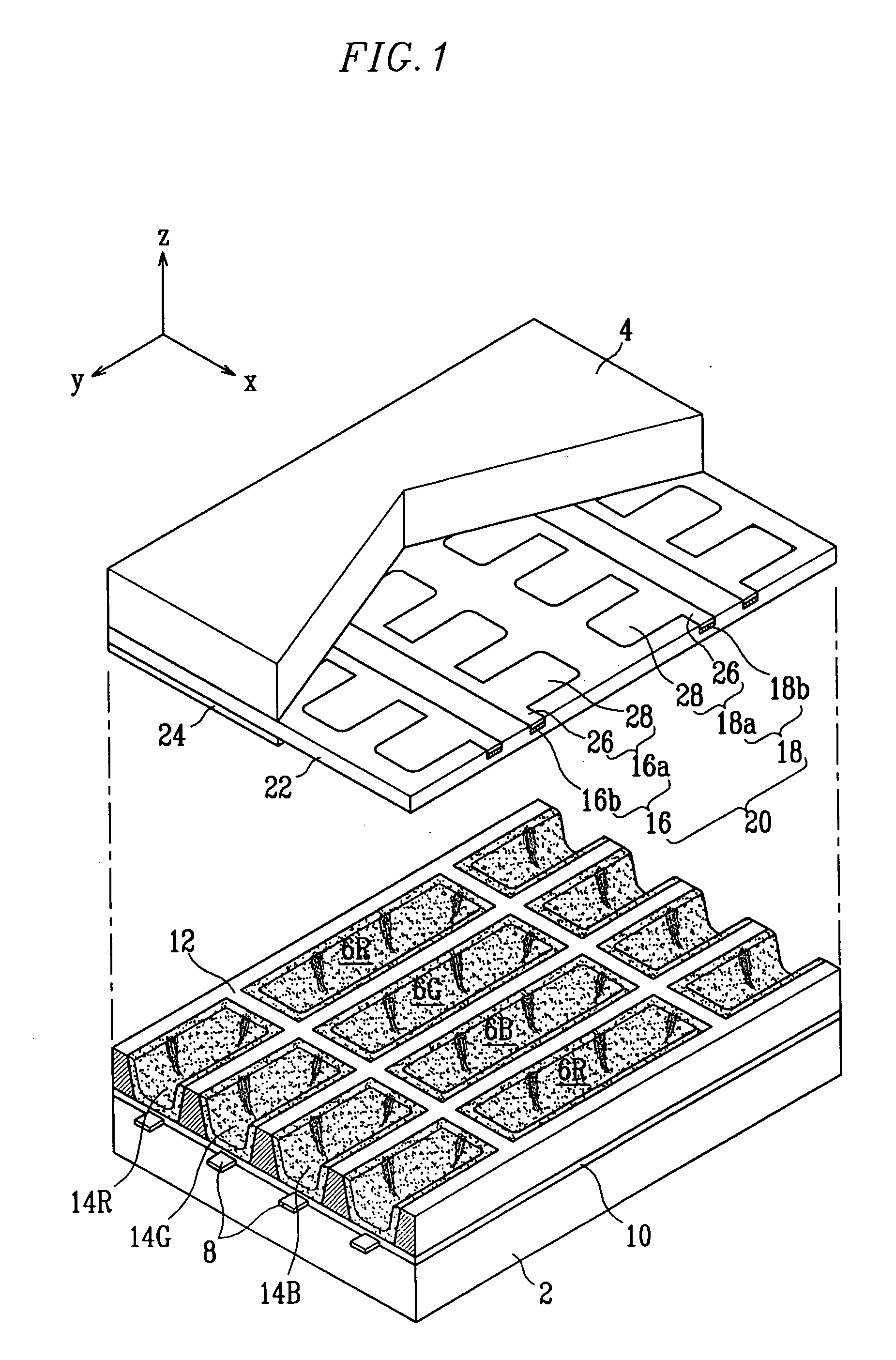
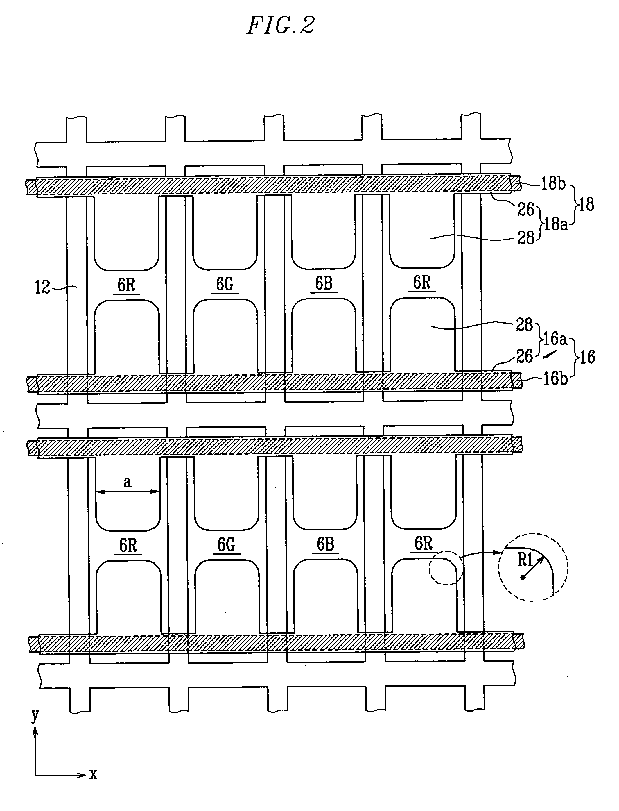
[0025] As shown in FIGS. 1 and 2, a Plasma Display Panel (PDP) according to the present invention includes a first substrate 2, a second substrate 4 facing the first substrate 2 and spaced apart therefrom, and discharge cells 6R, 6G, and 6B positioned between the first substrate 2 and the second substrate 4. A color image of the PDP is produced by visible light generated by each discharge cell 6R, 6G, and 6B operating with an independent discharge mechanism.

[0026] Address electrodes 8 are formed in one direction (y-axis direction) on the inner surface of the first substrate 2, and a first dielectric layer 10 is formed on the entire inner surface of the first substrate 2 to cover the address electrodes 8. The address electrodes 8 are arranged, for example, in stripe pattern so that each address electrode is in parallel to the neighboring address electrodes with a gap therebetween.

[0027] On top of the first dielectric layer 10, lattice-shaped barrier ribs 12 are formed in the extendi...

third embodiment

[0040] In a third embodiment as shown in FIG. 4, barrier ribs 34 are formed to define discharge cells 30R, 30G, and 30B and non-discharge regions 32. The discharge cells 30R, 30G, and 30B are arranged in a space in which a gas discharge and light emission are to occur, and the non-discharge region 32 is arranged in a space or region in which no gas discharge or light emission is to occur. The drawing shows an exemplary structure of the discharge cells 30R, 30G, and 30B and the non-discharge region 32 having respective independent cells.

[0041] The discharge cells 30R, 30G, and 30B defined by the barrier ribs 34 are optimized in shape for the propagation of the gas discharge in a manner that the region contributing substantially less to the sustain discharge and the luminance is shrunk. To be specific, both ends of each of the discharge cells 30R, 30G, and 30B in the extending direction (y-axis direction) of the address electrode becomes narrower in width as it goes away from the cent...


PUM


Abstract

A Plasma Display Panel (PDP), in which the precision level in shaping the display electrodes is improved by changing the shape of the transparent electrode, includes: address electrodes formed on a first substrate, barrier ribs defining discharge cells in a space between the first substrate and a second substrate and display electrodes, formed on the second substrate in a direction crossing the address electrodes, including a pair of line portions arranged on both sides of each discharge cell and having a pair of protrusion portions, facing each other, extending from the respective line portions toward the center of each discharge cell. The pair of the protrusion portions has rounded contours at both corners of each protrusion portion facing the paired protrusion portion and its radius R1 of curvature at the corner satisfies the following condition: 0.05a=R1=0.2a, where a is a width of the protrusion portion measured in the extending direction of the line portion.

Description

CLAIM OF PRIORITY [0001] This application makes reference to, incorporates the same herein, and claims all benefits accruing under 35 U.S.C. §119 from an application for PLASMA DISPLAY PANEL earlier filed in the Korean Intellectual Property Office on 4 Nov. 2004 and there duly assigned Serial No. 10-2004-0089275. BACKGROUND OF THE INVENTION [0002] 1. Field of the Invention [0003] The present invention relates to a Plasma Display Panel (PDP) and, in particular, to a PDP in which the shape of transparent electrode layers is changed for high precision in shaping display electrodes. [0004] 2. Description of the Related Art [0005] In general, a Plasma Display Panel (PDP) is a display device in which ultraviolet rays generated by a gas discharge excite phosphors to produce an image and has an advantage over a cathode ray tube due to its large screen with thin depth and high resolution. [0006] In a typical Alternating Current (AC) PDP, discharge cells are defined by barrier ribs placed bet...

Claims


Application Information

Patent Timeline
Patent Type & Authority Applications(United States)
IPC IPC(8): H01J17/49H01J11/12H01J11/22H01J11/24H01J11/26H01J11/34H01J11/36
CPCH01J11/12H01J11/24H01J2211/245
Inventor RHO, CHANG-SEOKCHIN, YOUNG-HOCHOI, JUNG-HYUCK
Owner SAMSUNG SDI CO LTD
Why Eureka
Try Eureka