Thermal flow rate sensor

a flow rate sensor and flow rate technology, applied in the direction of liquid/fluent solid measurement, process and machine control, instruments, etc., can solve the problems of linearity deterioration, low heat transfer efficiency, linearity degradation, etc., to improve the linearity enhance the level of process precision, and improve the effect of flow rate output characteristics

Inactive Publication Date: 2015-07-28
HORIBA STEC CO LTD
View PDF18 Cites 2 Cited by
  • Summary
  • Abstract
  • Description
  • Claims
  • Application Information

AI Technical Summary

Benefits of technology

[0011]With these arrangements, because the peak position of the temperature distribution generated by the upstream-side coil and the downstream-side coil is positioned on the upstream-side coil side relative to the middle position between the upstream-side coil and the downstream-side coil, it is possible to increase the amount of heat transferred to the downstream-side coil provided on the sensor flow path, by increasing the amount of heat taken by the fluid on the upstream side of the sensor flow path. As a result, it is possible to improve the linearity of the output obtained with the downstream-side coil. It is therefore possible to improve the linearity of the flow rate output characteristics of the thermal flow rate sensor and to enhance the level of precision of the process to measure an actual gas flow rate. Also, according to the present embodiment, because the upstream-side coil and the downstream-side coil that are each configured by using a heat-generating resistance wire are wound around the sensor flow pipe structuring the sensor flow path, it is possible to facilitate the heat transfer between the fluid flowing through the sensor flow path and the coils. It is therefore possible to make the advantageous effects of the present invention even more prominent.
[0012]It is desirable to set the temperature of the upstream-side coil to be higher than the temperature of the downstream-side coil. With this arrangement, it is possible to arrange the peak position of the temperature distribution generated by the upstream-side coil and the downstream-side coil to be positioned on the upstream-side coil side relative to the middle position between the upstream-side coil and the downstream-side coil, only by changing the resistance values of the fixed resistors in the one or more bridge circuits including the upstream-side coil and the downstream-side coil, without the need to change the configurations of the upstream-side coil and the downstream-side coil wound around the sensor flow pipe.
[0013]It is desirable to arrange the winding width of the upstream-side coil to be larger than the winding width of the downstream-side coil. With this arrangement, it is possible to arrange the peak position of the temperature distribution generated by the upstream-side coil and the downstream-side coil to be positioned on the upstream-side coil side relative to the middle position between the upstream-side coil and the downstream-side coil, only by adjusting the winding widths of the upstream-side coil and the downstream-side coil wound around the sensor flow pipe, without the need to change the circuit configurations of the one or more bridge circuits including the upstream-side coil and the downstream-side coil.
[0014]It is desirable to arrange the thermal flow rate sensor so as to include: an upstream-side constant temperature controlling circuit that has a bridge circuit including the upstream-side coil; and a downstream-side constant temperature controlling circuit that has a bridge circuit including the downstream-side coil. When constant-temperature control is exercised over the upstream-side coil and the downstream-side coil in this manner, because it is possible to measure the fluid flowing through the sensor flow path under a constant-temperature condition and because there is no need to take into consideration temperature fluctuations in a conversion factor (a gas-type conversion coefficient: a CF value), it is possible to obtain an actual gas flow rate value with a high level of precision.Advantageous Effects of Invention
[0015]According to an aspect of the present invention configured as described above, because the peak position of the temperature distribution generated in the sensor flow path by the upstream-side coil and the downstream-side coil is positioned on the upstream-side coil side relative to the middle position between the upstream-side coil and the downstream-side coil on the sensor flow path, it is possible to improve the linearity of the flow rate output characteristics of the thermal flow rate sensor and to enhance the level of precision of the process to measure the actual gas flow rate.

Problems solved by technology

However, when a gas having low thermal conductivity (e.g., SF6, CF4, or the like) is used, because the efficiency of the heat transfer is low in transferring the amount of heat taken from the upstream-side coil provided on the sensor flow path to the downstream-side coil provided on the sensor flow path, the linearity of the flow rate output characteristics of the thermal flow rate sensor with respect to the flow rate of the fluid flowing through the sensor flow path is not satisfactory.
In particular, a problem is that, as the flow rate of the fluid flowing through the sensor flow path increases, the output voltage Vd of the downstream-side constant temperature controlling circuit tends to become saturated so that the linearity deteriorates.
Thus, a problem arises where, when the standard curve of each thermal flow rate sensor is corrected by using the standard curve of a thermal flow rate sensor used as a reference, it is difficult to accurately perform, for example, a span correction on the standard curves by performing a one-point correction.
In other words, when the linearity of the standard curve of each thermal flow rate sensor is not maintained, even if a one-point correction is made, the level of precision of the corrections in the parts other than the one point is not satisfactory.
As a result, a problem arises where the level of precision of the process to measure an actual gas flow rate deteriorates.
The abovementioned problems occur not only with thermal flow rate sensors employing a constant temperature controlling method, but also with thermal flow rate sensors that employ a constant current controlling method and that include, as shown in FIG. 11, a bridge circuit structured by connecting an upstream-side coil and a downstream-side coil in series and a constant current circuit that causes a constant current to flow through the bridge circuit.

Method used


Image

  • Thermal flow rate sensor
  • Thermal flow rate sensor
  • Thermal flow rate sensor

Examples


Embodiment Construction

[0027]Exemplary embodiments of a thermal flow rate sensor according to the present invention will be explained with reference to the drawings.

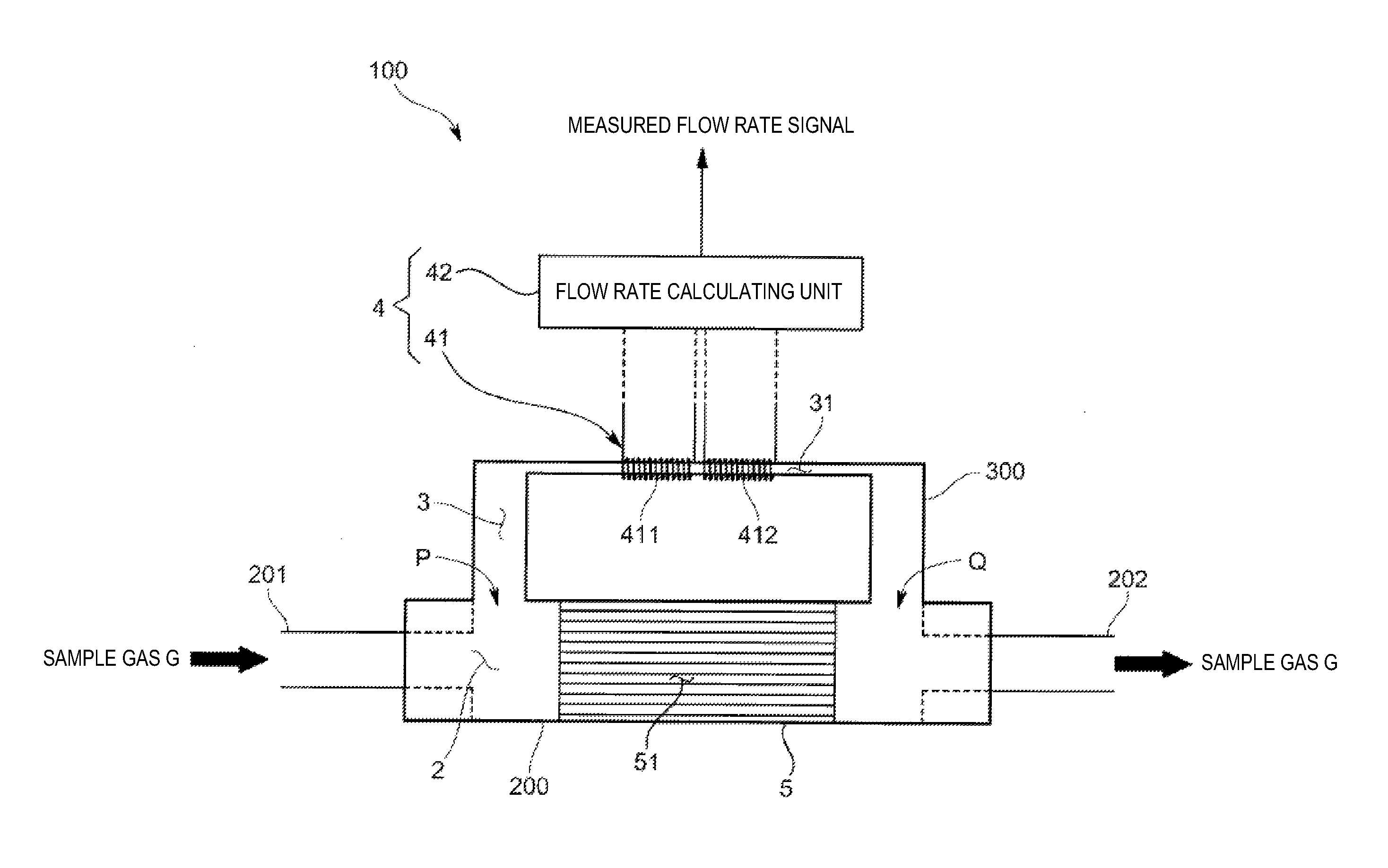
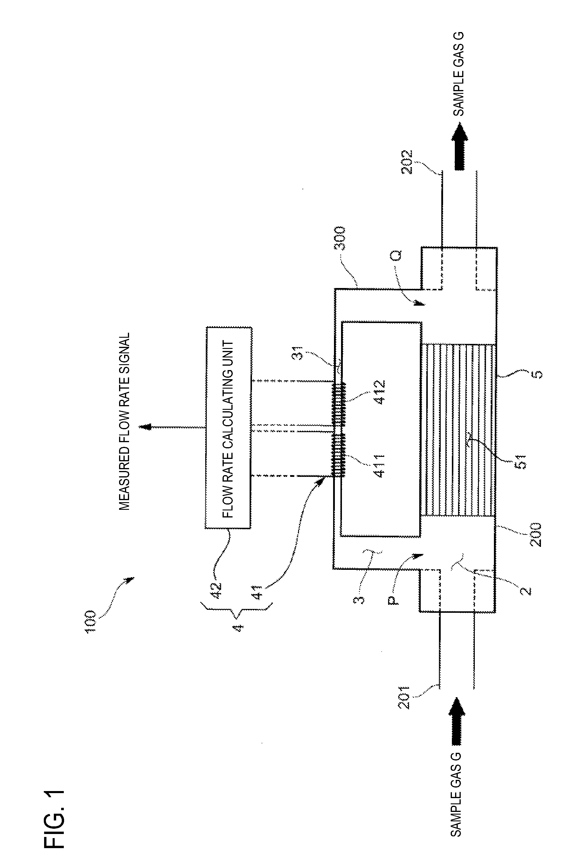
[0028]A thermal flow rate sensor 100 according to an embodiment is a thermal mass flow rate sensor that is used in, for example, a semiconductor production process and includes, as shown in FIG. 1: a main flow path 2 through which a sample gas G (a fluid) (e.g., a semiconductor process gas such as SF6) flows; a sensor flow path 3 that branches off from the main flow path 2 so as to cause the sample gas G to flow in a split flow and to detect a flow rate of the sample gas G; a flow rate detecting mechanism 4 that is configured to detect the flow rate of the sample gas G; and a laminar flow element 5 serving as a resistive element that is provided in the main flow path 2 so as to be positioned between a split point P and a junction point Q of the sensor flow path 3 and that includes a plurality of internal flow paths 51. The laminar flow element...


PUM


Abstract

A thermal flow rate sensor is provided which includes a main flow path through which a fluid flows, and a sensor flow path that branches off from the main flow path so as to cause the fluid to flow in a split flow and that is provided with a flow rate detecting mechanism configured to detect a flow rate of the fluid. The flow rate detecting mechanism includes an upstream-side coil and a downstream-side coil, each configured by using a heat-generating resistance wire wound around a sensor flow pipe forming the sensor flow path. A peak position of a temperature distribution generated in the sensor flow path by the upstream-side coil and the downstream-side coil is positioned on the upstream-side coil side relative to the middle position between the upstream-side coil and the downstream-side coil on the sensor flow path.

Description

TECHNICAL FIELD[0001]The present invention relates to a thermal flow rate sensor.BACKGROUND ART[0002]An example of conventional thermal flow rate sensors includes, as described in Patent Document 1: a main flow path through which a fluid flows; and a sensor flow path that branches off from the main flow path so as to cause the fluid to flow in a split flow and is provided with a flow rate detecting mechanism configured to detect a flow rate of the fluid.[0003]An example of the flow rate detecting mechanism is configured so that, as shown in FIG. 10, a sensor flow pipe forming the sensor flow path is provided with an upstream-side coil and a downstream-side coil that are independent of each other and that are each configured by using a heat-generating resistor of which the resistance value changes in accordance with temperature, the flow rate detecting mechanism being further provided with: an upstream-side constant temperature controlling circuit that has a bridge circuit including ...

Claims


Application Information

Patent Timeline
Patent Type & Authority Patents(United States)
IPC IPC(8): G01F1/684G01F1/696G05D7/06
CPCG01F1/684G01F1/6842G01F1/696G05D7/0635
Inventor OKANO, HIROYUKISHIRAI, TAKASHI
Owner HORIBA STEC CO LTD
Why Eureka
Try Eureka