Supercharge Your Innovation With Domain-Expert AI Agents!

Clock scaling circuit

a clock and scaling circuit technology, applied in the direction of generating/distributing signals, pulse techniques, instruments, etc., can solve the problems of malfunctioning of the circuit, inappropriate introduction of multi-cycle dead time,

Active Publication Date: 2006-05-04
GLOBALFOUNDRIES US INC
View PDF11 Cites 20 Cited by
  • Summary
  • Abstract
  • Description
  • Claims
  • Application Information

AI Technical Summary

Problems solved by technology

However, this switching may cause glitches on clock lines resulting in malfunctioning of the circuit.
However, introducing multi-cycle dead time is inappropriate for certain applications, such as built in self test circuits.

Method used


Image

  • Clock scaling circuit
  • Clock scaling circuit
  • Clock scaling circuit

Examples


Embodiment Construction

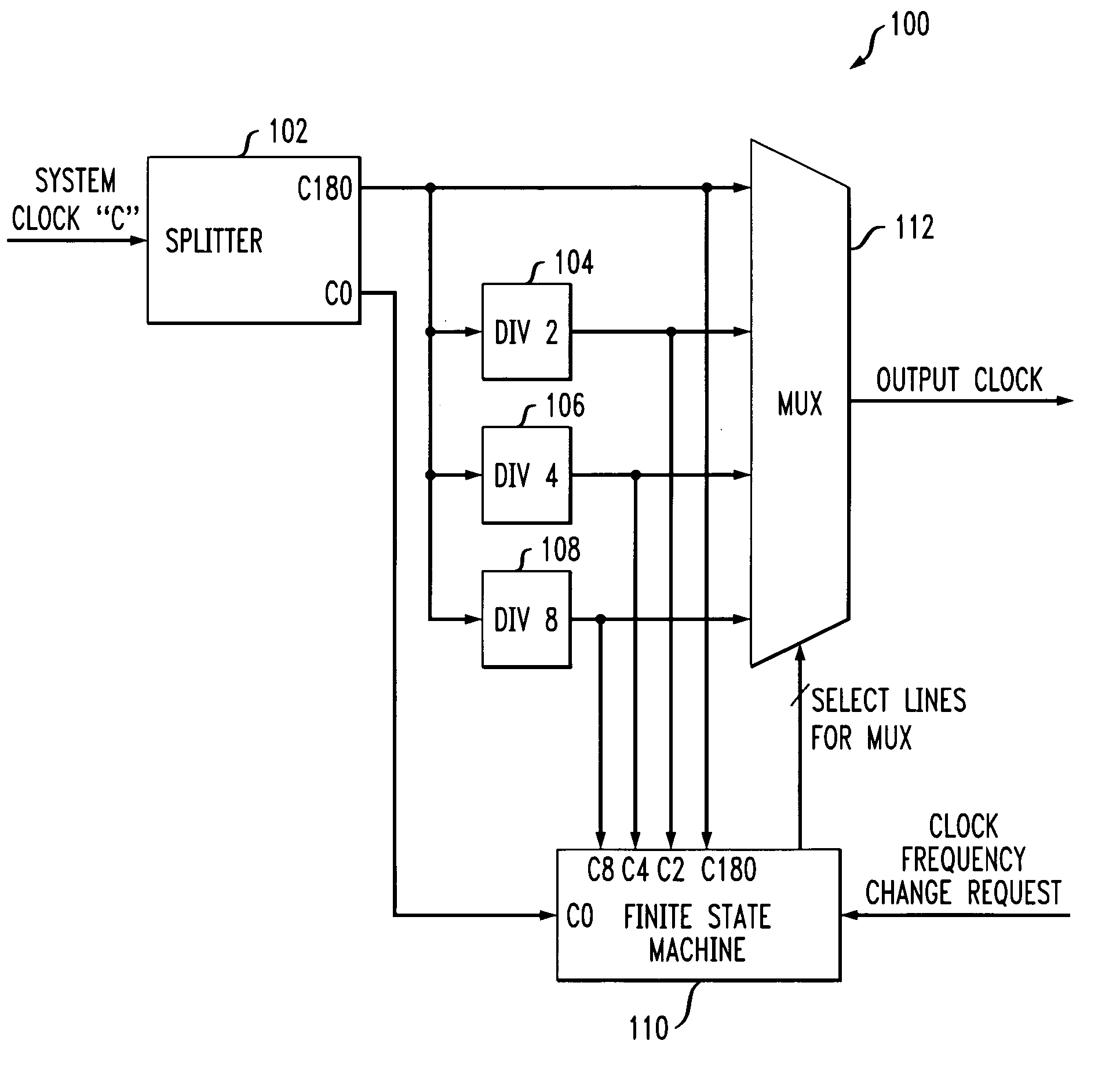
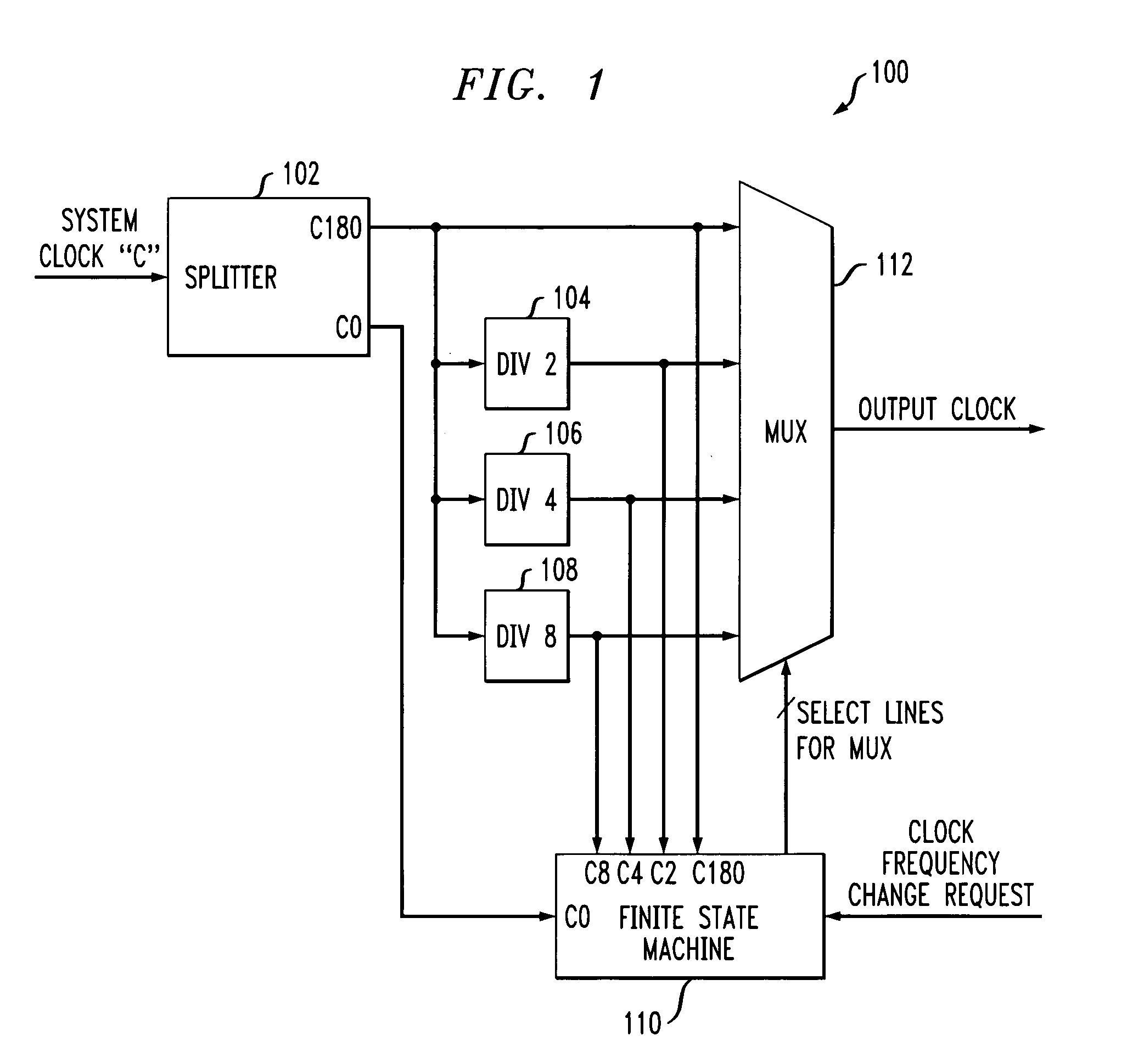
[0021] Referring initially to FIG. 1, a diagram illustrates a frequency clock signal generation and switching circuit, according to an embodiment of the present invention. In general, the circuit shown in FIG. 1 may also be referred to herein as a clock scaling circuit.

[0022] More particularly, FIG. 1 depicts a circuit for sub-system frequency clock signal generation and switching in a glitch-free manner. As shown, circuit 100 includes a clock splitter 102, clock divide-by-2 circuit 104, clock divide-by-4 circuit 106, clock divide-by-8 circuit 108, finite state machine 110, and multiplexer 112.

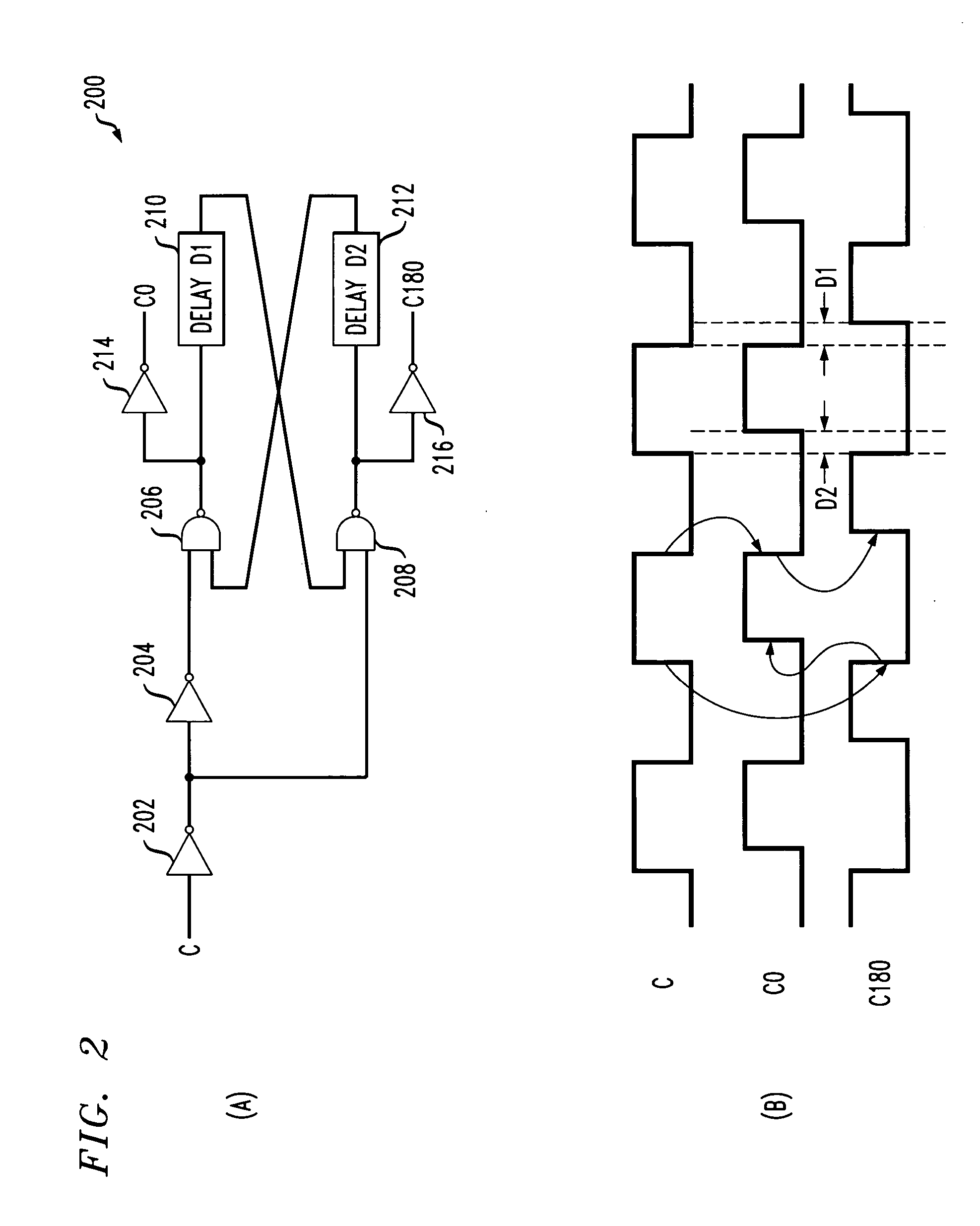
[0023] In accordance with principles of the invention, circuit 100 generates two clock signals (e.g., C0 and C180) from the system clock (C) which needs to be scaled or divided. The new clock signals C0 and C180 are 180 degrees out of phase from each other. C0 is designed to be in phase with C and C180 is designed to be out of phase with C. This operation can be achieved using clock splitter...


PUM


Abstract

Techniques for scaling and switching clocks in a glitch-free manner are provided. For example, in one aspect of the present invention, a technique for switching a frequency associated with a master clock includes the following steps / operations. Two phase clocks are generated from a master clock, wherein the two phase clocks do not transition at substantially the same time. Then, one of the two phase clocks is used to create multiple frequencies by dividing the one phase clock, and the other phase clock is used to switch between the multiple frequencies of the one phase clock. Further, one of the two phase clocks may be in phase with the master clock and the other of the two phase clocks may be 180 degrees out of phase with the master clock such that they do not transition at the same time. Also, the two phase clocks may be non-overlapping.

Description

FIELD OF THE INVENTION [0001] The present invention generally relates to low power circuits, built in self test circuits and, more particularly, to clock generation and scaling circuits. BACKGROUND OF THE INVENTION [0002] Low power applications, as well as certain high performance applications, typically require a slowing down of the system clock by dividing the system clock and switching the circuit to a low frequency clock, and then back to a higher frequency, as required by the application. [0003] Such clock switching circuits are also used in built in self test (BIST) circuits for dynamic fault detection. These BIST circuits determine the optimum clock frequency at which the associated circuit under test can be run error-free. [0004] This switching of clock lines from one frequency to another is called clock scaling and is typically done “on the fly” without turning off the circuit. However, this switching may cause glitches on clock lines resulting in malfunctioning of the circ...

Claims


Application Information

Patent Timeline
IPC IPC(8): G06F1/04
CPCG06F1/06G06F1/08
Inventor KAPUR, MOHIT
Owner GLOBALFOUNDRIES US INC
Features
  • R&D
  • Intellectual Property
  • Life Sciences
  • Materials
  • Tech Scout
  • Unparalleled Data Quality
  • Higher Quality Content
  • 60% Fewer Hallucinations
Learn More