Single-fiber launch/receive system for biosensing applications

Inactive Publication Date: 2006-05-04
CORNING INC
View PDF27 Cites 79 Cited by
  • Summary
  • Abstract
  • Description
  • Claims
  • Application Information

AI Technical Summary

Problems solved by technology

However, one of the main drawbacks of a launch/receive system that uses optical fiber is the difficulty and poor efficiency of coupling light into the fiber core.
But, the sensor output poses a much more challenging task.
As such, the coupling efficiency from the optical sensor into the fiber is poor, and large-area multimode fibers are sometimes employed to alleviate thi

Method used


Image

  • Single-fiber launch/receive system for biosensing applications
  • Single-fiber launch/receive system for biosensing applications
  • Single-fiber launch/receive system for biosensing applications

Examples


Example

DETAILED DESCRIPTION OF THE DRAWINGS

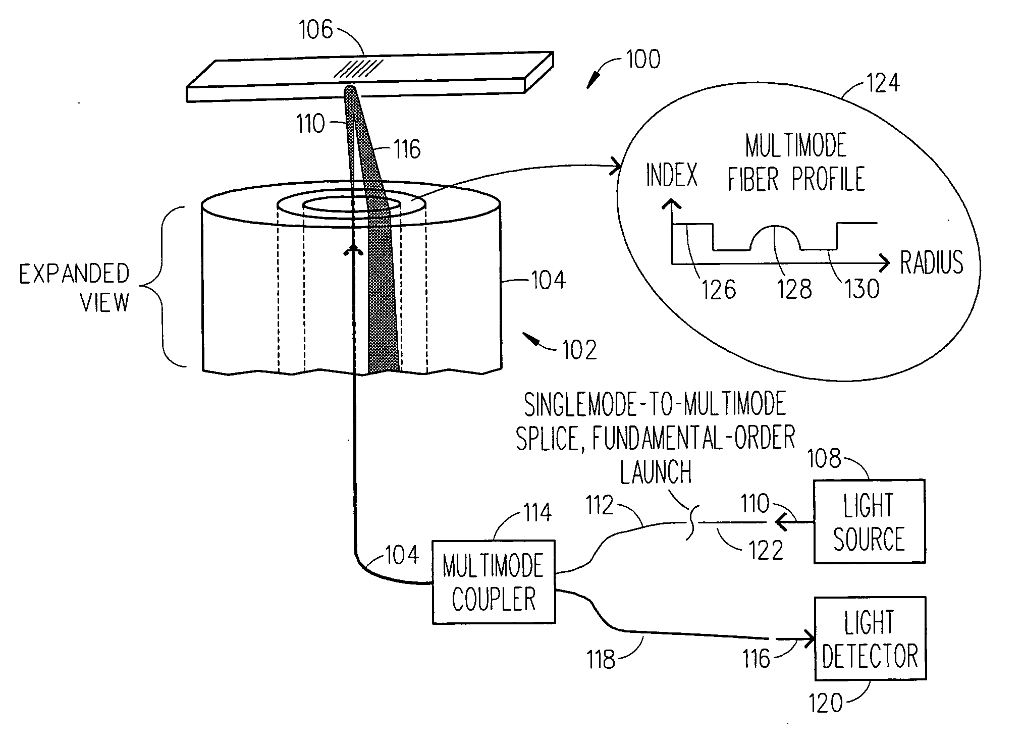
[0015] Referring to FIG. 1, there is a diagram that illustrates an interrogation system 100 which includes a single-fiber launch / receive system 102 that uses a multimode fiber 104 (preferably graded-index multimode fiber) to interface with a biosensor 106 to detect the occurrence of a bio-chemical interaction (e.g., biological binding of ligands to analytes) on top of the biosensor 106. As shown, the interrogation system 100 includes a light source 108 (e.g., SLED, laser, etc. 108) that outputs a light beam 110 into a fiber optic cable 122 (e.g., singlemode fiber optic cable 122). This fiber is spliced to a graded-index multimode fiber cable 112, which under the proper alignment couples the single-mode beam 110 from the cable 122 into the fundamental (lowest-order) mode of the multimode fiber cable 112, thereby preserving the “single-modedness” of the source. While graded-index fiber 112 is preferable as it easily preserves the fundamental mode p...


PUM


Abstract

An interrogation system and method are described herein which use a single-fiber launch/receive system for interrogating a biosensor (optical sensor) to detect the occurrence of a bio-chemical interaction (e.g., biological binding of ligands with analytes). In one embodiment, the single-fiber launch/receive system utilizes a multimode fiber to help interrogate the biosensor. In another embodiment, the single-fiber launch/receive system utilizes a downjacketed singlemode fiber to help interrogate the biosensor.

Description

BACKGROUND OF THE INVENTION [0001] 1. Field of the Invention [0002] The present invention relates in general to optical non-contact sensor technology and more particularly to an interrogation system which uses a single-fiber launch / receive system for interrogating a biosensor to detect the occurrence of a bio-chemical interaction (e.g., biological binding of ligands with analytes). [0003] 2. Description of Related Art [0004] Many areas of biological research today utilize optical non-contact sensor technology to help perform increasingly sensitive and time-constrained assays. In such assays, an optical interrogation system can be used to monitor changes in the refractive index or variations in the optical response of an optical sensor (biosensor) as a biological substance is brought into a sensing region of the optical sensor. The presence of the biological substance alters the optical response of the optical sensor when it causes a bio-chemical interaction like material binding, ad...

Claims


Application Information

Patent Timeline
IPC IPC(8): G02B6/26
CPCG01N21/253G02B6/02G02B6/4246
Inventor MOZDY, ERIC J.
Owner CORNING INC
Why Eureka
Try Eureka