Apparatus and method for combining multiple optical beams in a free-space optical communications system

a technology of optical communication system and apparatus, applied in the field of apparatus and method for combining multiple optical beams in a free-space optical communication system, can solve the problems of existing network infrastructure and technology reaching their limits, expensive approach, and expensive approach, and achieve the effect of increasing the power level of the optical signal

Inactive Publication Date: 2005-03-15
OL SECURITY LIABILITY CO
View PDF21 Cites 62 Cited by
  • Summary
  • Abstract
  • Description
  • Claims
  • Application Information

AI Technical Summary

Problems solved by technology

As network demands continue to increase, existing network infrastructures and technologies are reaching their limits.
This is a very costly approach, however.
As before, this approach is costly.
However, use of such a coupler results in significant power loss on the output side of the coupler.
Thus, a large portion of the amplification is lost via the coupler.
A significant drawback of this scheme is that it only supports optical signals with very low power levels.

Method used


Image

  • Apparatus and method for combining multiple optical beams in a free-space optical communications system
  • Apparatus and method for combining multiple optical beams in a free-space optical communications system
  • Apparatus and method for combining multiple optical beams in a free-space optical communications system

Examples


embodiment 10

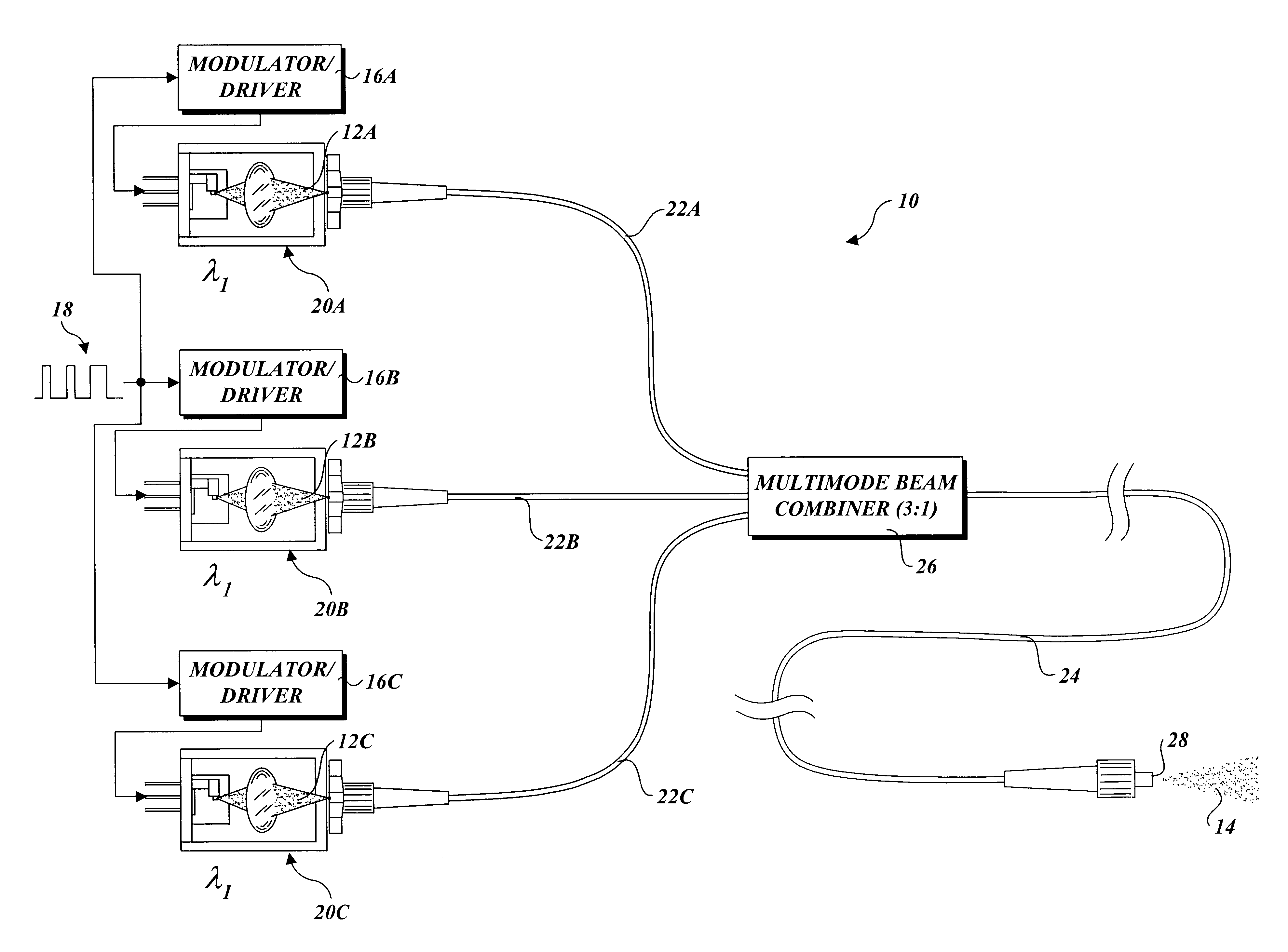
In accordance with one aspect of the invention, various configurations are disclosed herein that enable a plurality of redundant optical signals to be combined into a single signal and transmitted to a receiving terminal via an FSO link. For example, an embodiment 10 shown in FIG. 1 enables three optical signals 12A, 12B, and 12C corresponding to there redundant channels A, B, and C to be combined into a single mode-scrambled optical signal 14, which then may be transmitted using appropriate optics (not shown) to a receiving terminal (not shown) at the other end of an FSO link. Each channel A, B, and C includes a respective modulator / driver 16A, 16B, and 16C that receives a common input data stream 18 as an input and generates a corresponding modulate drive current that is used to drive a laser diode in a respective laser beam source 20A, 20B, and 20C. Optionally, a single multi-channel modulator / driver may be used in place of the individual modulator drivers. The laser beam sources...

an embodiment 30

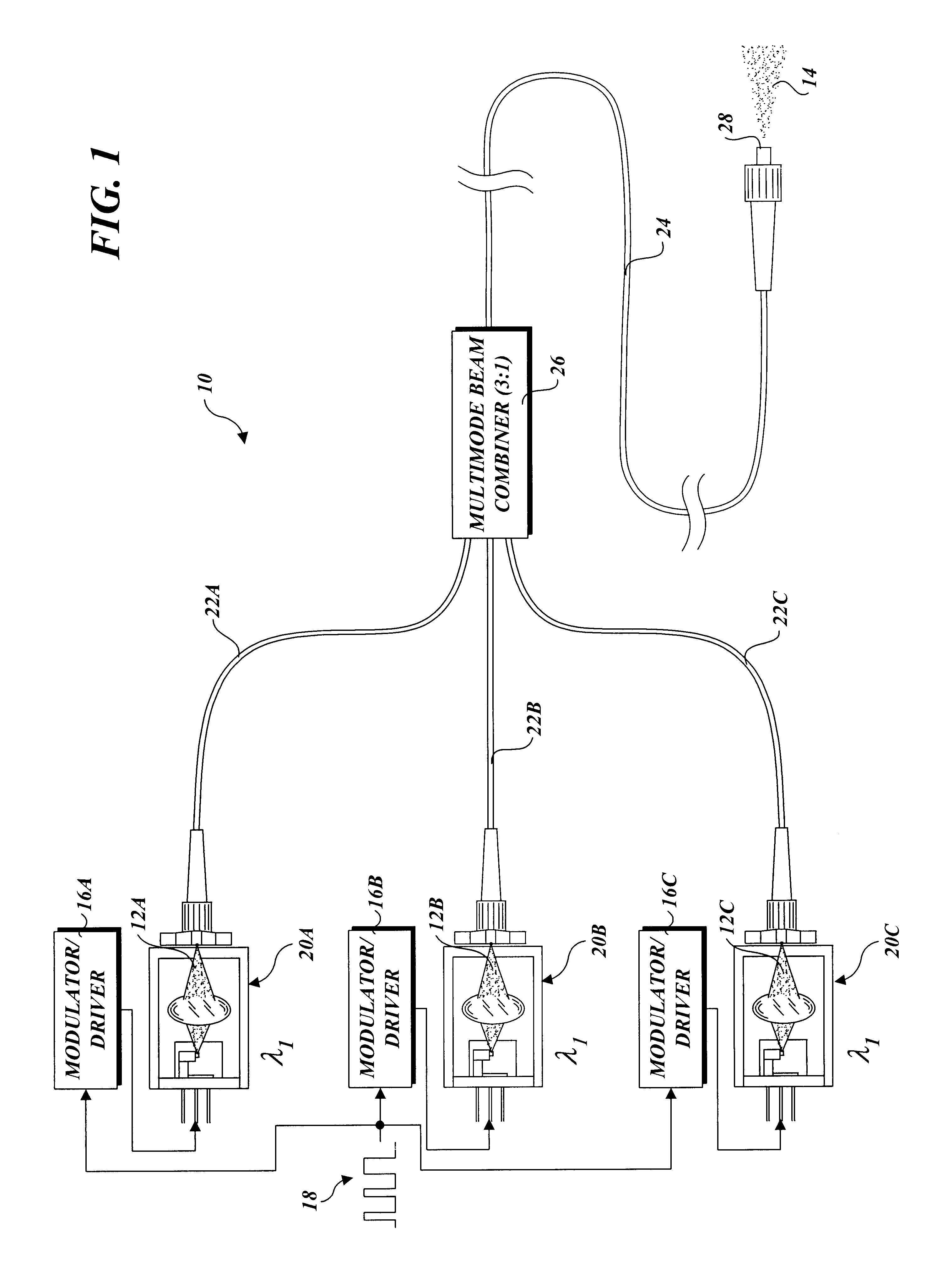
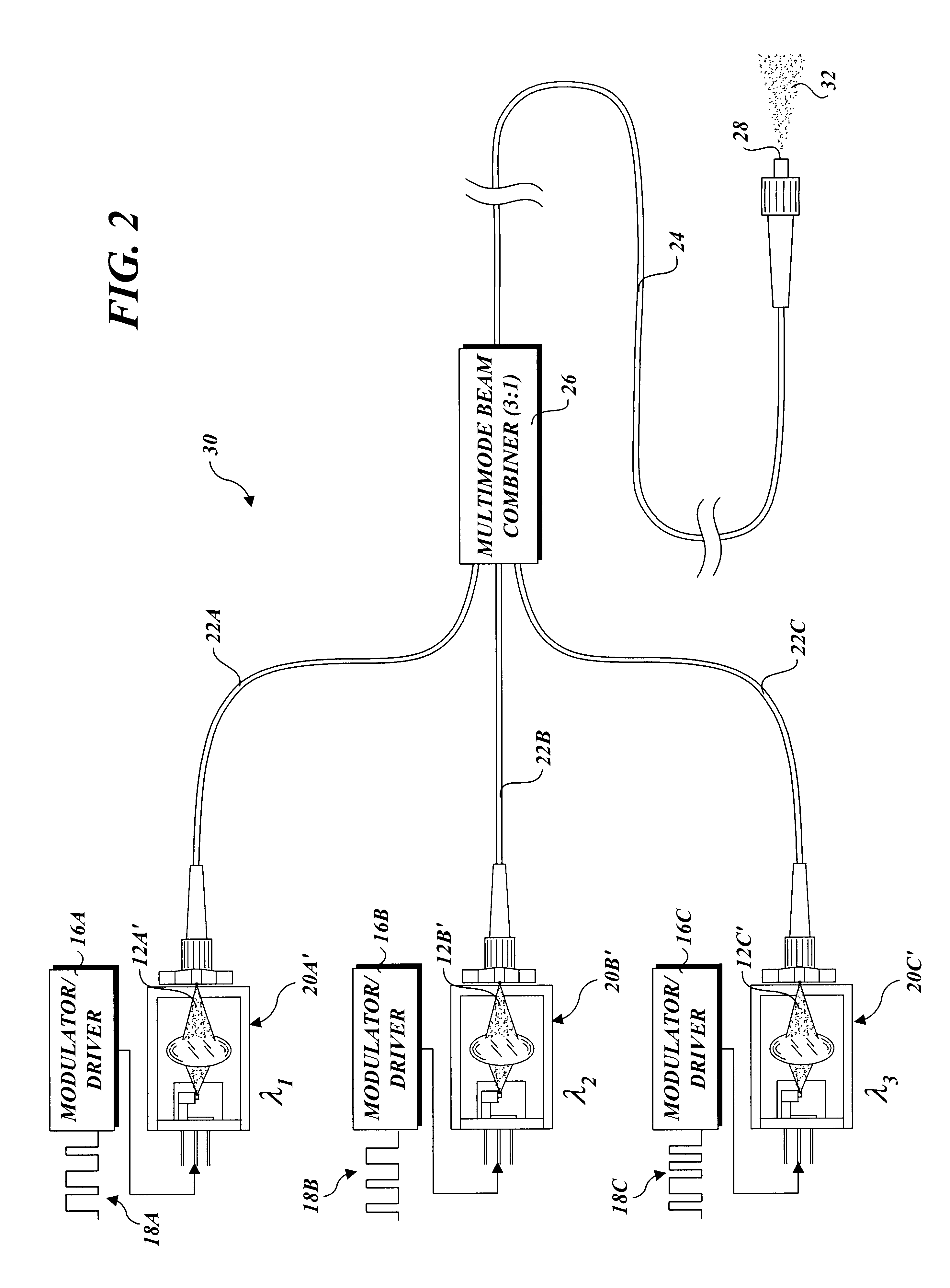
An embodiment 30 that enables data pertaining to multiple independent data streams 18A, 18B, and 18C to be transmitted simultaneously via a wavelength division multiplexed (WDM) signal 32 is shown in FIG. 2. In this configuration, each of independent data streams 18A, 18B, and 18C is received by a respective modulator / driver 16A, 16B, and 16C. The modulator / drivers, in turn, provide modulated currents to drive respective laser diodes in laser sources 20A′, 20B′ and 20C′ to produce respective optical signals 12A′, 12B′, and 12C′. Each of optical signals 12A′, 12B′, and 12C′ has a separate wavelength, as depicted by wavelengths λ1, λ2, and λ3.

By using multiple modulated signals having respective wavelengths, the bandwidths of each of the individual signals can be aggregated, thereby increasing the bandwidth of an FSO link. Generally, the wavelength spacing should meet that prescribed for Course Wavelength Division Multiplexing (CWDM), i.e., near 1550 nanometers (nm) with a nominal 20 ...

an embodiment 10 ′

An embodiment 10′, which is a variant of embodiment 10, is shown in FIG. 3. In this embodiment, a portion of output fiber segment 24 is configured in a series of alternating loops 34. It is noted that the final segment of multimode fiber may be configured in a similar series of alternating loops for each of the embodiments discussed herein, and that FIG. 3 is merely representative of a particular implementation corresponding to embodiment 10. Experimental results have shown that the use of such alternating loops improves the mode scrambling of a mode-scrambled optical signal in which the outer portions of the numerical apertures of the signal are more filled.

Details of alternating loops 34 in accordance with one embodiment are shown in FIG. 4. In this embodiment, the alternating loops may be formed by wrapping a portion of output fiber segment 24 around a plurality of rods 38 in an alternating manner. In general, the radius R of the loops should be large enough to not cause damage t...


PUM


Abstract

An apparatus and method for combining multiple optical beams into mode-scrambled optical signals. In one embodiment, the apparatus includes a plurality of laser beam sources, each to produce a modulated optical beam. A plurality of input fiber segments, each comprising a multimode optical fiber core, are operatively coupled at one end to a respective laser source to receive a respective modulated optical beam. A multimode optical beam combiner is used to operatively couple the output ends of the input fiber segments to the input end of an output fiber segment having a multimode optical fiber core. The modulated optical beams produced by the laser beam sources are combined into a single mode-scrambled optical signal. The apparatus enables multiple optical beams having similar wavelengths to be combined to increase optical signal strength. It also enables multiple optical beams having different wavelengths to be combined to form a wavelength division multiplexed signal.

Description

BACKGROUND OF THE INVENTION1. Field of the InventionThe present invention generally relates to free-space optical (FSO) communications systems, and, more specifically, to an apparatus and method for efficiently combining a plurality of single-mode or multi-mode fiber-coupled optical beams into single fiber-coupled multimode optical beam.2. Background InformationWith the increasing popularity of wide area networks (WANs), such as the Internet and / or the World Wide Web, network growth and traffic has exploded in recent years. Network users continue to demand faster networks and more access for both businesses and consumers. As network demands continue to increase, existing network infrastructures and technologies are reaching their limits.An alternative to present day hardwired or fiber network solutions is the use of wireless optical communications. Wireless optical communications utilize point-to-point communications through free-space and therefore do not require the routing of cab...

Claims


Application Information

Patent Timeline
Patent Type & Authority Patents(United States)
IPC IPC(8): H04B10/13H04B10/2581
CPCG02B6/2804H04B10/2581G02B6/4204G02B6/4207
Inventor WILTSEY, THOMAS J.ROLLINS, DAVID L.PIERCE, ROBERT M.
Owner OL SECURITY LIABILITY CO
Why Eureka
Try Eureka