Multimode optical fibers with increased bandwidth

a multi-mode optical fiber and bandwidth technology, applied in the field of multi-mode optical fibers with increased bandwidth, can solve the problems of inherent defects and perturbations, and achieve the effect of enhancing mode mixing

Inactive Publication Date: 2006-05-09
FURAKAWA ELECTRIC NORTH AMERICA INC
View PDF17 Cites 55 Cited by
  • Summary
  • Abstract
  • Description
  • Claims
  • Application Information

AI Technical Summary

Problems solved by technology

These perturbations exist as inherent “defects” even in high quality optical fiber.

Method used


Image

  • Multimode optical fibers with increased bandwidth
  • Multimode optical fibers with increased bandwidth
  • Multimode optical fibers with increased bandwidth

Examples


Embodiment Construction

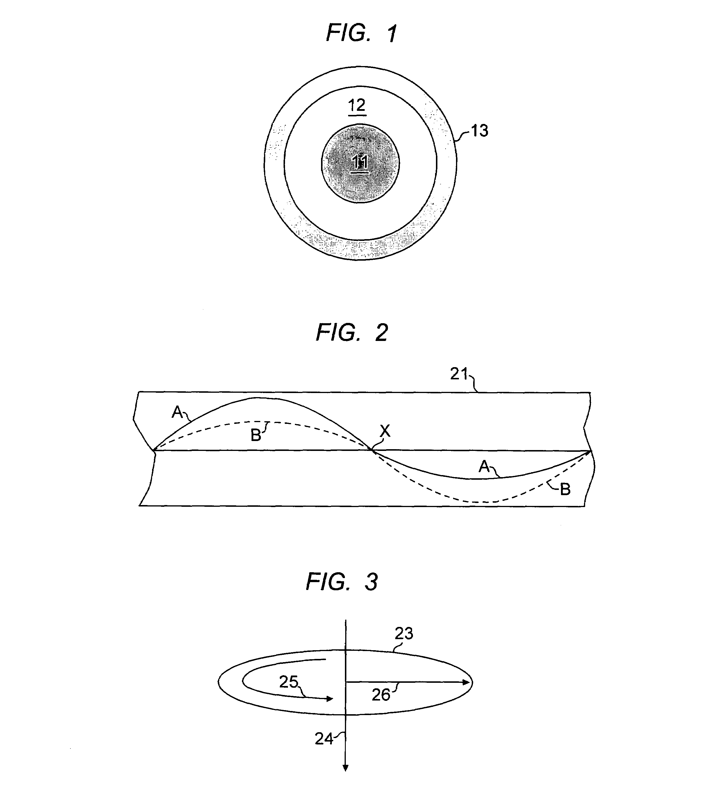
[0018]Referring to FIG. 1, a typical multimode optical fiber structure is shown with core 11 and cladding 12. A standard polymer protective coating, typically an acrylate polymer, is shown at 13.

[0019]The multimode characteristic of the optical fiber is represented by the relative size of core 11, and the shaded representation of the index variation from the center to the outside of the core. There are three common types of multimode fiber. These may be defined by the core / cladding diameter, expressed in microns:[0020]50 / 125—FDDI standard; used for data communications;[0021]62.5 / 125—FDDI standard for local data communications (and the most prevalent multi-mode fiber in use in North America);[0022]100 / 140—designed for specialized applications where light coupling efficiency and bending sensitivity are important.

[0023]As a general proposition, multimode fiber has a core / clad diameter ratio greater than 0.2, and typically greater than 0.4. This can be compared to single mode fiber with...


PUM

PropertyMeasurementUnit
diameteraaaaaaaaaa
core radiusaaaaaaaaaa

Abstract

The specification describes a technique for drawing circular core multimode optical fiber using twist during draw to increase fiber bandwidth.

Description

RELATED APPLICATION[0001]This application is a division of application Ser. No. 10 / 027,067, filed Dec. 20, 2001, now U.S. Pat. No. 6,735,985, issued Mat 18, 2004.FIELD OF THE INVENTION[0002]This invention relates to multimode optical fibers having increased bandwidth.BACKGROUND OF THE INVENTION[0003]Manufacture of state of the art multimode optical fiber requires demanding control over a variety of power loss and signal impairment mechanisms. For multimode fiber, controlling mode dispersion is an important goal.[0004]As is well known, within the optical fiber, bits of data are represented by pulses of light. Each pulse of light will spread, or disperse, over time as it travels the length of the fiber. If these data pulses overlap, they can no longer be unambiguously read at the receiving end. Lower tendency toward data pulse overlap results in higher data transmission capacity, i.e. higher bandwidth. Therefore, the bandwidth of optical fibers is ultimately limited by dispersion.[000...

Claims


Application Information

Patent Timeline
Patent Type & Authority Patents(United States)
IPC IPC(8): G02B6/036C03B37/027C03B37/03C03B37/12G02B6/02G02B6/028
CPCC03B37/02745C03B37/032G02B6/0288G02B6/02C03B2203/36C03B2205/06G02B6/02395G02B6/02285G02B6/03627C03B2203/19
Inventor DIGIOVANNI, DAVID JOHNDIMARCELLO, FRANK VINCENTJIANG, XINLIOULUNDSEN, GEORGE E.PANDIT, SANDEEP PRABHAKAR
Owner FURAKAWA ELECTRIC NORTH AMERICA INC
Why Eureka
Try Eureka