Alignment method for circular multi-core optical fiber

a multi-core, optical fiber technology, applied in the direction of optical elements, cladded optical fibres, instruments, etc., can solve the problems of difficult and difficult to obtain precise alignment of the individual positions of the cores of the circular multi-core optical fiber, and achieve the effect of increasing the amount of light and/or light characteristi

Inactive Publication Date: 2009-06-16
IBM CORP
View PDF12 Cites 30 Cited by
  • Summary
  • Abstract
  • Description
  • Claims
  • Application Information

AI Technical Summary

Benefits of technology

[0009]In yet a further aspect of an embodiment of the present invention, the method provides adjusting a position of the second end of the multi-core fiber; wherein, the at least one core fiber is position to increases the amount of light and / or light characteristic to be detected at the second end of the multi-core fiber.

Problems solved by technology

The complexity involved in identifying and precisely aligning the individual positions of each core of a circular multi-core fiber cable is difficult and not easily obtained.

Method used


Image

  • Alignment method for circular multi-core optical fiber
  • Alignment method for circular multi-core optical fiber
  • Alignment method for circular multi-core optical fiber

Examples


Embodiment Construction

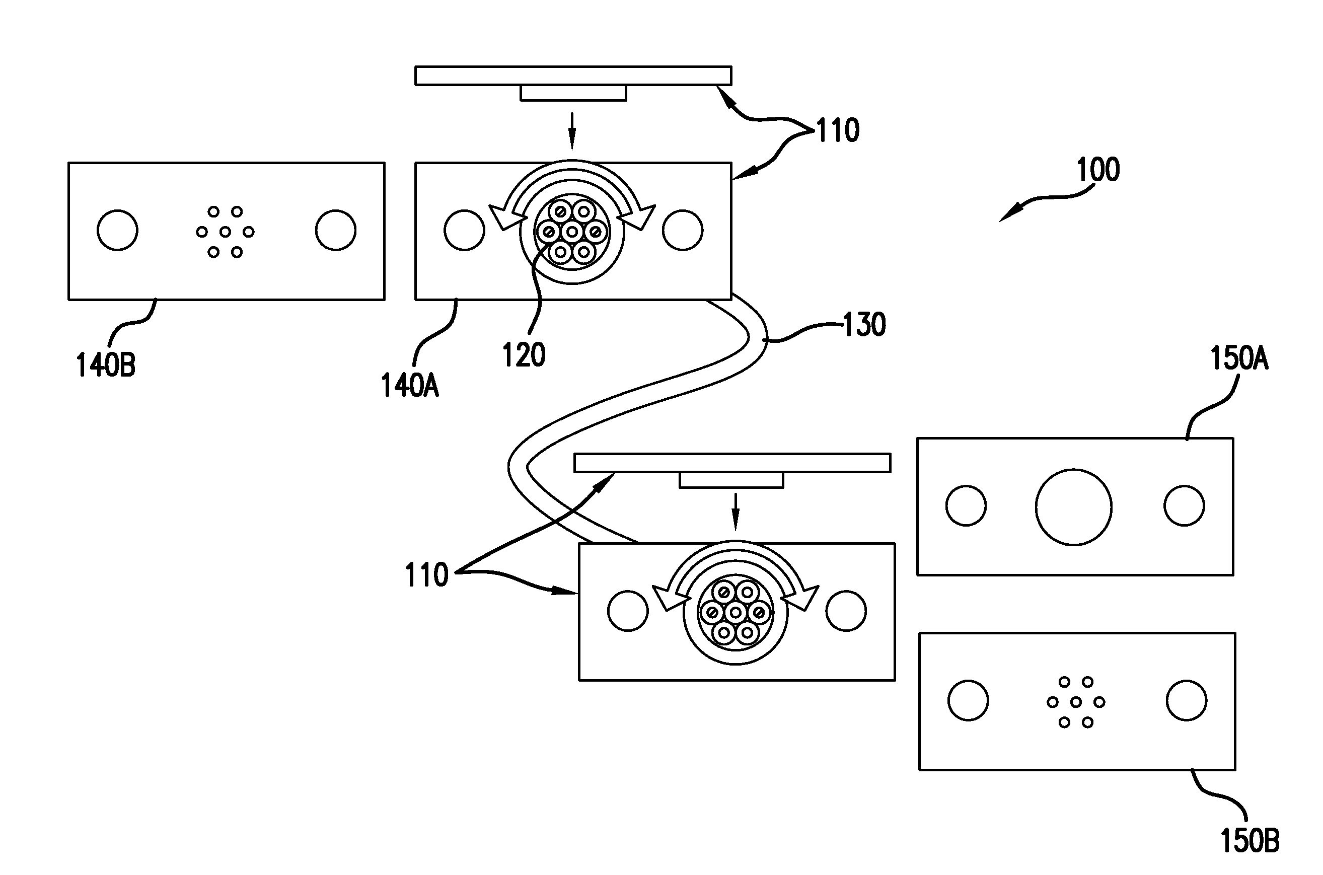
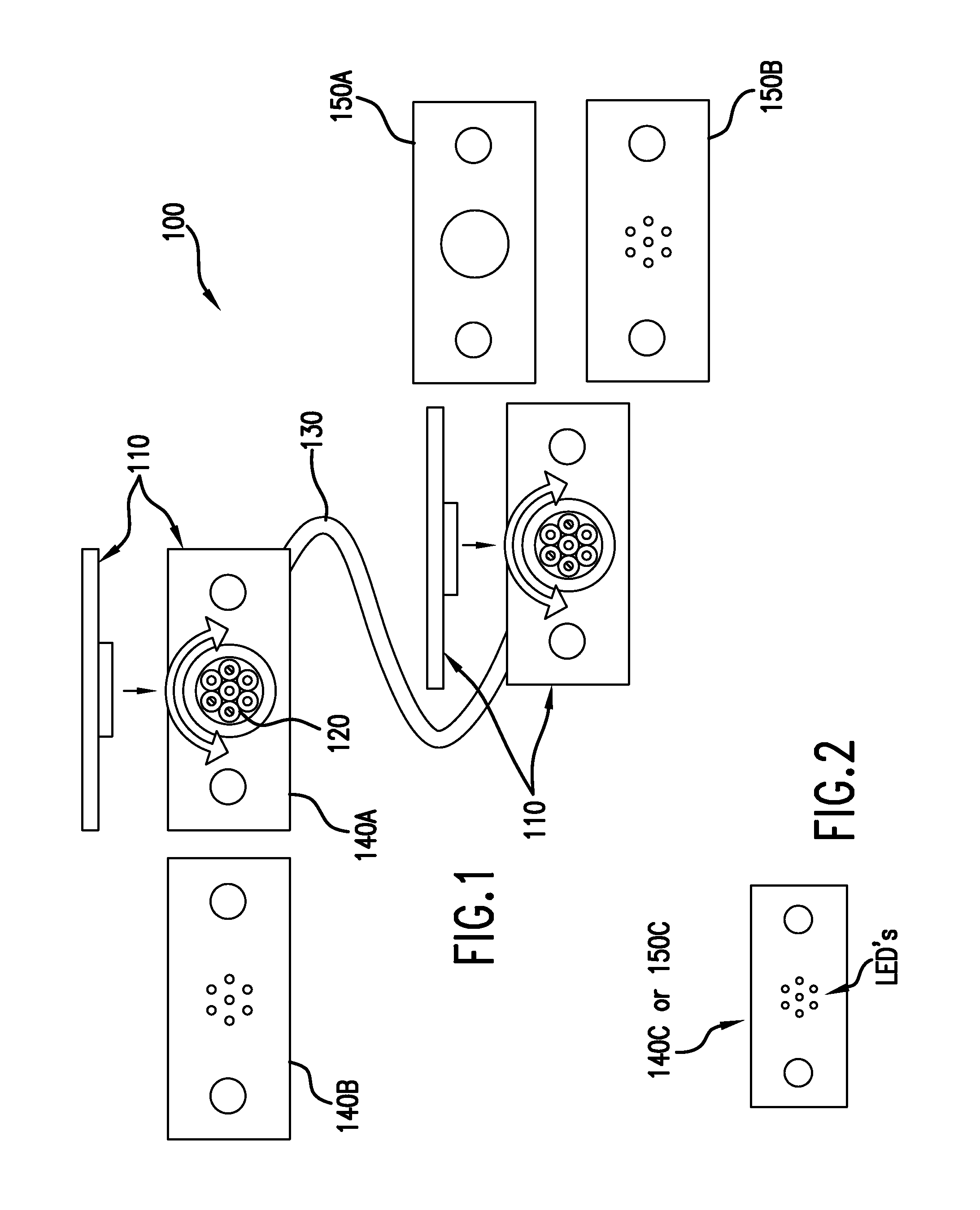
[0016]As shown in FIG. 1, there may be two light types of light input and receiving alignment structures. The first type of alignment structure is shown in FIG. 1, and has been labeled as light input device 140A, the other has been depicted as device 140B. Light input device 140A allows the incident light from the input source to be aligned to first end of the multi-core fiber 120. In this step each core position is aligned to the incident light structure. Since, the light input receiving device 140A detects the whole amount of transmitted light the second end of the multi-core fiber 130 does not need to be aligned at this time. This makes it easier and more efficient to align the individual core input end to the light input device 140A.

[0017]The second type of alignment structure is shown in FIG. 1, and has been labeled as light receiving device 150B, similarly there is a corresponding light receiving structure depicted as device 150A. Light receiving device B, allows the incident ...


PUM


Abstract

The present invention relates to a method of aligning circular multi-core fibers, wherein the method utilized independent and individually selected cores to receive, transmit, and emit light from input devices. The present invention further relates to positioning the ends of a multi-core fiber in order to detect and determine the precise locations of individually selected core fibers.

Description

CROSS REFERENCE TO RELATED APPLICATIONS[0001]There are no cross-references to this application.FIELD OF THE INVENTION[0002]The present invention relates to a method and / or tool for multi-core optical fiber alignment and more particularly to a method and / or tool for using light input into specific individual cores, to achieve precise alignment of a multi-core optical fiber cable. Relevant potential applications for this invention include the fabrication of optical fiber cable, and communication transmissions utilizing optical fiber cables as interfaces for coupling devices.BACKGROUND OF THE INVENTION[0003]As the performance of computer systems has accelerated, optical high density transmission devices have been utilized to replace electronic devices. The use of optical devices for transmitting and receiving provides greater bandwidth and thus allows great amounts of data to be transferred.[0004]Multi-core cable may utilize a continuous molding process. The use of the multi-core fiber...

Claims


Application Information

Patent Timeline
Patent Type & Authority Patents(United States)
IPC IPC(8): G02B6/26G02B6/04G02B6/42
CPCG02B6/40G02B6/4249G02B6/036G02B6/42
Inventor HORIBE, AKIHIROYAMADA, FUMIAKITAIRA, YOICHI
Owner IBM CORP
Why Eureka
Try Eureka