

Multi-core optical fiber, optical connector and method of manufacturing multi-core optical fiber
a technology of optical connectors and optical fibers, applied in the direction of manufacturing tools, cladded optical fibres, instruments, etc., can solve the problems of difficult optical connection between the core portion and the vcsel element, and the difficulty of fabricating the vcsel array in which the vcsel elements are arranged as closely as such
- Summary
- Abstract
- Description
- Claims
- Application Information
AI Technical Summary
Problems solved by technology
Method used
Image

Examples
first embodiment
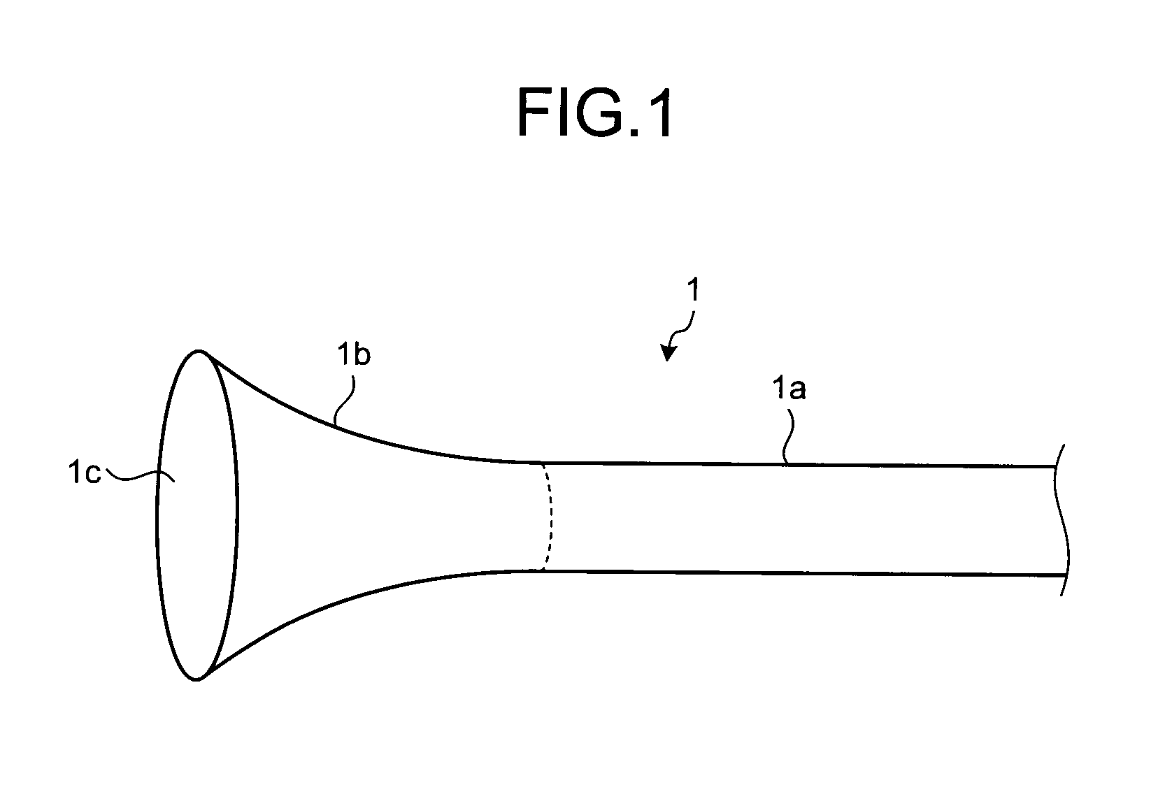
[0029]Firstly, a multi-core optical fiber according to a first embodiment will be described in detail. FIG. 1 is a schematic diagram of the multi-core optical fiber according to the first embodiment. As shown in FIG. 1, the multi-core optical fiber 1 has a cylindrical portion 1a of which external diameter is approximately even along a longitudinal direction, and a reverse-tapered portion 1b juncturally connecting with the cylindrical portion 1a while gradually spreading toward one edge 1c along the longitudinal direction.
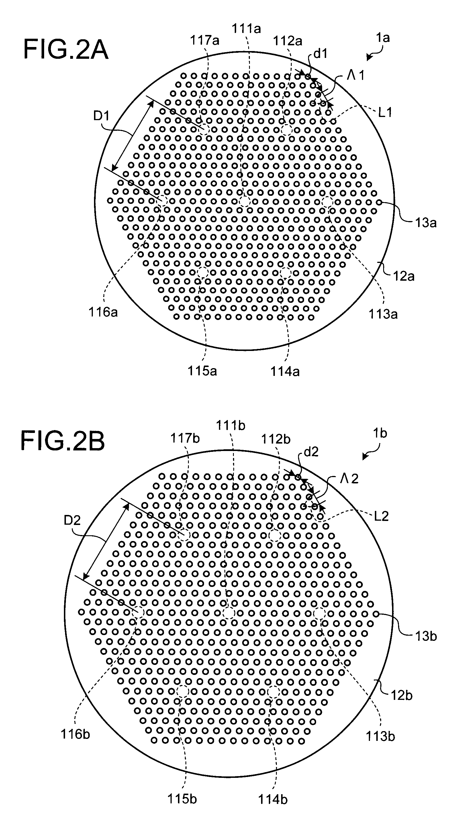
[0030]FIG. 2A is a cross-sectional view of a cylindrical portion 1a of the multi-core optical fiber 1 shown in FIG. 1 showing a cross-section perpendicular to a longitudinal direction. FIG. 2B is a cross-sectional view of a reverse-tapered portion 1b of the multi-core optical fiber 1 shown in FIG. 1 showing a cross-section perpendicular to a longitudinal direction. FIG. 2A shows a cross-section of the cylindrical portion 1a, and FIG. 2B shows a cross-section of the ...
second embodiment
[0062]The multi-core optical fiber 1 according to the first embodiment is a holey fiber type optical fiber. Although, it can also be a multi-core optical fiber with a type of confining light to the core portion by using a refractive index difference between a core portion and a cladding portion which are formed by mediums with refractive indexes different from each other. In the following, a multi-core optical fiber confining light to the core portion using a refractive index difference will be described in detail. The multi-core optical fiber according to the second embodiment has a cylindrical portion and a reverse-tapered portion as the multi-core optical fiber 1 shown in FIG. 1.
[0063]FIG. 9 is a schematic diagram of an edge surface of a multi-core optical fiber according to the second embodiment. As shown in FIG. 9, the multi-core optical fiber 9 has core portions 911 to 917 arranged so as to be separated from each other and a cladding portion 92 located around the core portions...
third embodiment
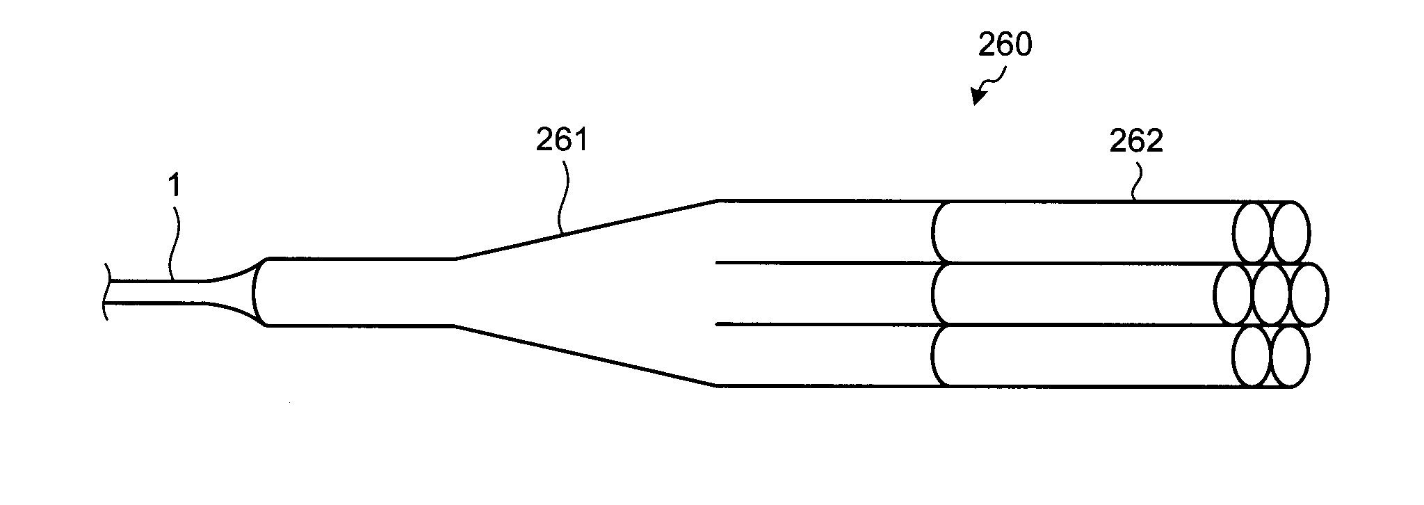
[0065]Next, an optical connector having the multi-core optical fiber 1 according to the first embodiment will be described as a third embodiment of the present invention. FIG. 10 is a block diagram showing a structure of an optical communication system using an optical connector according to a third embodiment. As shown in FIG. 10, the optical communication system 200 has an optical transmitter 210 which outputs a signal light, an optical transmission channel 230 which transmits the signal light outputted from the optical transmitter 210, and an optical receiver 250 which receives the signal light transmitted via the optical transmission channel 230 and processes the signal light. Between the optical transmitter 210 and the optical transmission channel 230 and between the optical transmission channel 230 and the optical receiver 250, optical connectors220 and 240 according to the third embodiment are arranged, respectively, for connection between the two.
[0066]The optical transmitte...
PUM
| Property | Measurement | Unit |
|---|---|---|
| Diameter | aaaaa | aaaaa |
| Speed | aaaaa | aaaaa |
Abstract
Description
Claims
Application Information