Plastic landscape border system

a landscape border and plastic technology, applied in the field of landscape edging systems, can solve the problems of inconvenient installation, difficult connection end-to-end of logs or ties, and inability to provide a light weight system

Inactive Publication Date: 2006-05-11
LOVE JIMMY L
View PDF15 Cites 3 Cited by
  • Summary
  • Abstract
  • Description
  • Claims
  • Application Information

AI Technical Summary

Benefits of technology

[0008] The landscape edging system of the present invention provides a plurality of lightweight components that adjustably interlock to form a landscape timber or tie capable of conforming to contours of a flowerbed or other landscape structure in need of a border. A main body component is hollow and made in the shape of a wood landscape timber or tie. End mountable and replaceable male connector components, female connector components and a three-way connector components are provided to interconnect the main body components to form any desired pattern, including the building of retaining walls. An anchor stake pipe is provided at each connection to serve as an axel around which the main body components may be radially adjusted, the stake pipe being driven into the ground as desired to avoid shifting of the system components. The three-way joint feature allows the system to be used as anchor ties for retaining walls.

Problems solved by technology

Logs or ties offer attractive, rustic appeal to a lawn or garden but have the deficiencies of substantial weight in handling and deterioration due to rotting or weather.
Such logs or ties are also difficult to connect end-to-end, straight or at an angle to form a desired, overall landscape feature such as a polygonal shape.
Some edging systems provide types of end-to-end connections but none provide a light weight system easily installed including both two-way and three-way connections.

Method used


Image

  • Plastic landscape border system
  • Plastic landscape border system
  • Plastic landscape border system

Examples


Embodiment Construction

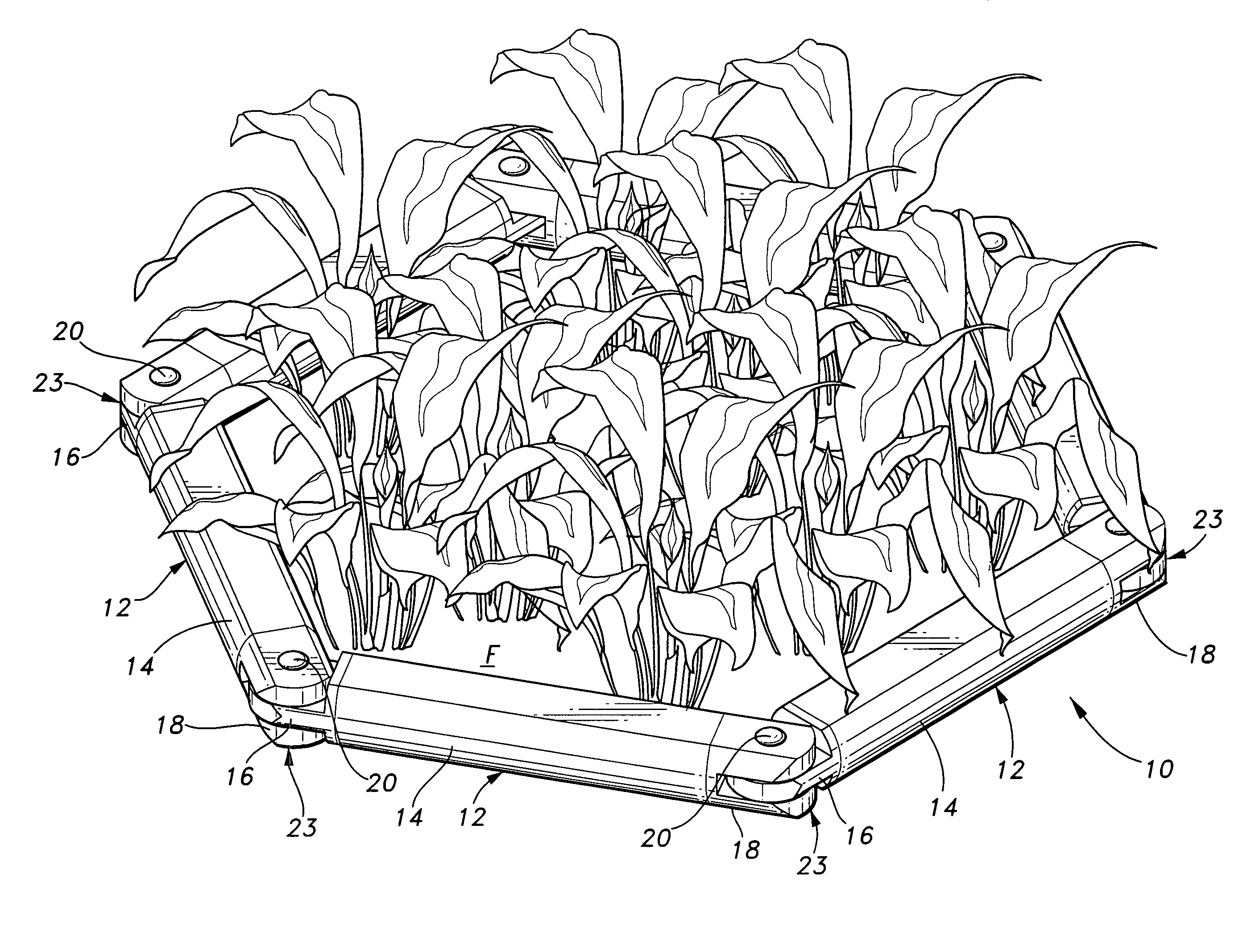
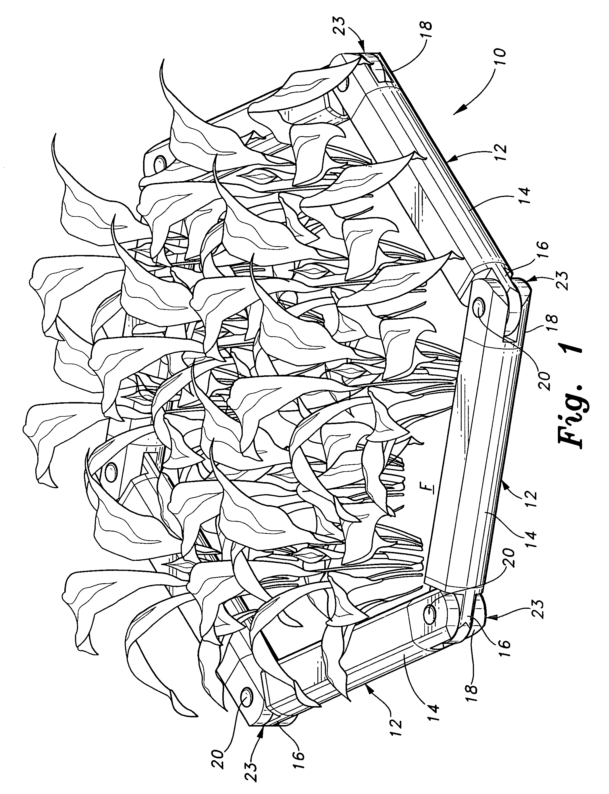
[0018] The present invention is a lightweight edging system for landscaping simulating wooden logs or ties.

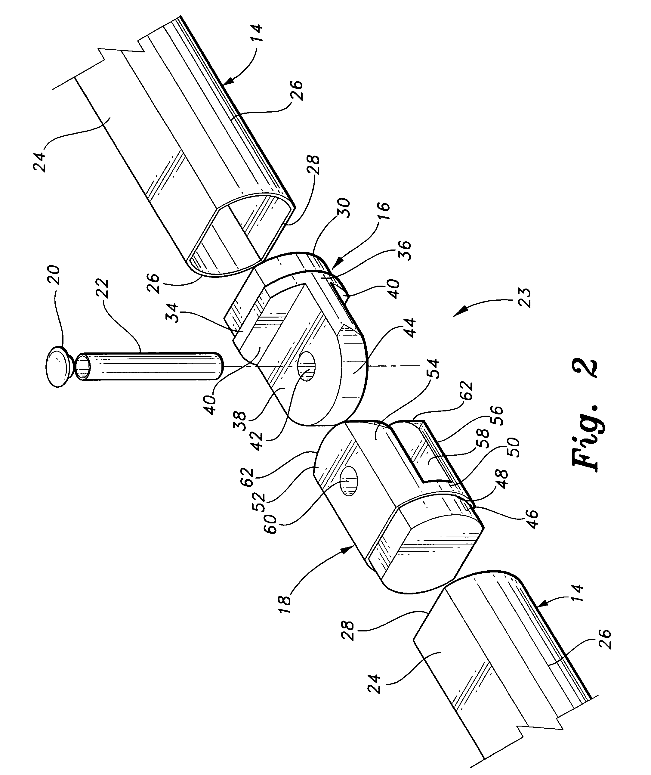
[0019] Referring to FIGS. 1 and 2, there are shown an environmental perspective and a detail exploded view of a two-way joint embodiment of the inventive landscape edging system. Landscape edging system 10 is shown surrounding flower bed F and includes log or tie units 12 having tubular main body units 14, each having a male connector 16 and a female connector 18 mounted at respective opposed ends thereof. Succeeding male and female connectors are interconnected in the manner of a hinge by anchor pipe stake 22 acting as an anchor and an axle or pivot pin, the top of which is covered by pipe stake cover 20 and forming successive two-way joints 23.

[0020] As best seen in FIG. 2, main body elements 14 have horizontal walls 24 and generally vertical sidewalls 26 having opposing main body ends 28. Male connectors 16 and female connectors 18 are each slideably and frictionally engag...


PUM


Abstract

A landscape edging system interlocks to form a landscape timber or tie capable of conforming to contours of a flowerbed or other landscape structure in need of a border. A main body component is hollow and made in the shape of a wood landscape timber or tie. End mountable and replaceable male connector components, female connector components, and three-way connector components are provided to interconnect the main body components to form any desired pattern, including the building of retaining walls. An anchor stake pipe is provided at each connection to serve as and axel around which the main body components are radially adjusted, the stake pipe being driven into the ground as desired to avoid shifting of the system components. The timber or tie is simulated by lightweight tubular plastic.

Description

CROSS-REFERENCE TO RELATED APPLICATION [0001] This application claims the benefit of U.S. Provisional Patent Application Ser. No. 60 / 622,052, filed Oct. 27, 2004.BACKGROUND OF THE INVENTION [0002] 1. Field of the Invention [0003] The present invention relates to landscape edging system. More particularly, the present invention relates to log or tie-like edging systems having rotatable joints. [0004] 2. Description of the Related Art [0005] Existing landscape edging is traditionally partially rounded brick set edge to edge to separate one landscape feature from another such as a driveway or flowerbed from a lawn. Other edging systems include vertical, plastic or rubber edging which is held by stakes or are partially buried. It is also common to employ logs or railroad ties or the like as landscape edging. These logs or ties may also be laid on each other to form a low fence or retaining wall. Logs or ties offer attractive, rustic appeal to a lawn or garden but have the deficiencies o...

Claims


Application Information

Patent Timeline
Patent Type & Authority Applications(United States)
IPC IPC(8): A01G23/10
CPCA01G1/08A01G9/28
Inventor LOVE, JIMMY L.
Owner LOVE JIMMY L
Why Eureka
Try Eureka