Opening and closing valve

US20060096642A1Active Publication Date: 2006-05-11TOTO LTD

Image

  • Opening and closing valve
  • Opening and closing valve
  • Opening and closing valve

Examples


Embodiment Construction

[0062] With reference to accompanying drawings, an embodiment of the present invention will now be described.

[0063] Firstly, with reference to FIGS. 1 to 7(b), a pilot-controlled switching valve assembly according to a first embodiment of the present invention will be described. This assembly is applied to a mixing faucet.

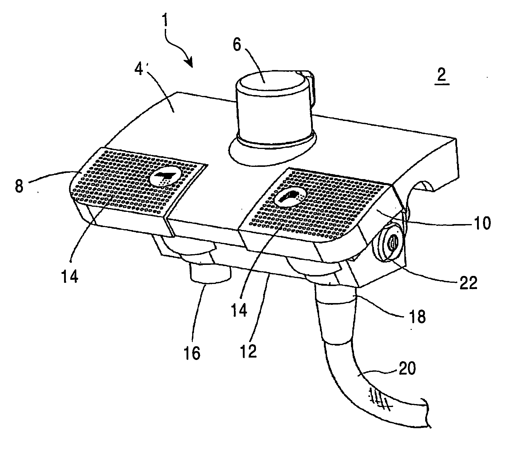
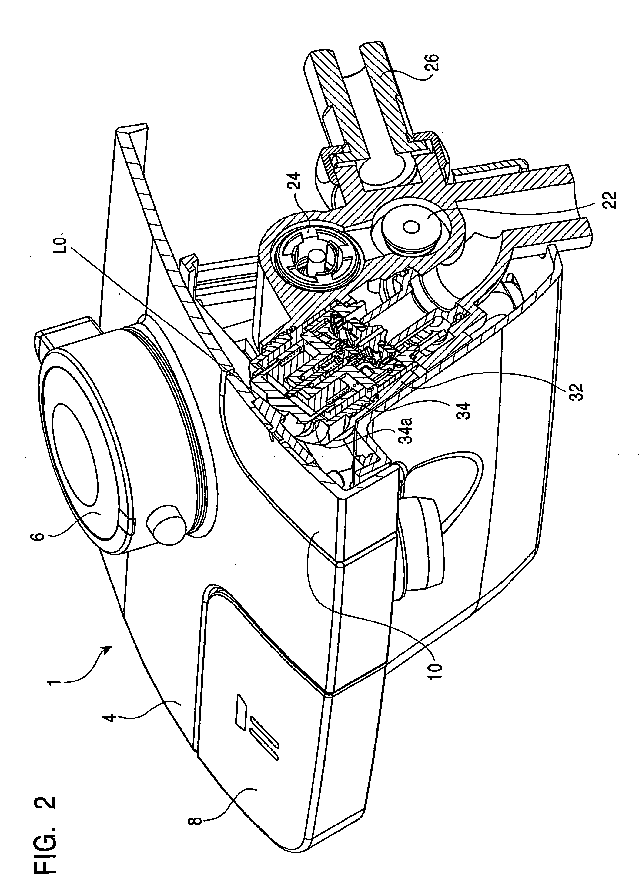
[0064]FIG. 1 is a general perspective view showing the mixing faucet to which the pilot-controlled switching valve assembly according to the first embodiment of the present invention is to be applied.

[0065] As shown in FIG. 1, the mixing faucet indicated by the reference numeral 1 is attached onto a wall surface 2, which is an installation surface of the mixing faucet 1, in such a manner as to protrude therefrom. The mixing faucet 1 comprises a plate-shaped heat-insulating cover 4 which is a part of a faucet body. The mixing faucet 1 further includes a temperature-adjusting dial 6, a faucet push button 8 for discharging mixed water from a faucet, and a shower pu...


PUM


Abstract

A switching valve assembly 32 for use in a mixing faucet is disclosed. The switching valve assembly comprises a switching valve assembly 32 for use in a mixing faucet, which comprises a manual operation member 36 adapted to be moved in response to a pressing operation by a user, a push rod 35 having a base end joined to the manual operation member, a pilot valve 40 disposed relative to a distal end of the push rod, a coil spring 42 interposed between the pilot valve and the distal end of the push rod, a diaphragm main valve 46 having a pilot-valve port designed such that the pilot valve is selectively brought into contact therewith and separated therefrom, a pressure chamber 48 formed on the side of a back surface of the main valve to contain a part of the push rod, the pilot valve and the coil spring, and a valve seat 52 designed such that a front surface of the main valve is selectively seated thereon and unseated therefrom.

Description

TECHNICAL FIELD [0001] The present invention relates to a switching valve assembly, and more particularly to a switching valve assembly for use in a mixing faucet operable to mix hot water and cold water at a desired temperature and selectively stop and discharge the mixed water. BACKGROUND ART [0002] Heretofore, a pilot-controlled switching valve assembly has been known which comprises a main valve and a pilot valve for opening and closing the main valve, and various types of pilot-controlled switching valve assemblies have been proposed. [0003] Fundamentally, all types of pilot-controlled switching valve are provided with (1) a manual operation member, such as a button, (2) a pilot valve movable in conjunction with the manual operation member, (3) a main valve and a pressure chamber disposed on the side of a back surface of the main valve, and designed to open the main valve in response to releasing a primary pressure in the pressure chamber by use of the pilot valve. [0004] A spe...

Claims


Application Information

Patent Timeline
11 May 2006
Publication
US20060096642A1
IPC
F16K31/365; E03C1/04; E03C1/044; F16K11/00; F16K21/12; F16K31/128; F16K31/145; F16K31/385
CPC
E03C1/04; E03C2201/30; F16K11/00; F16K21/12; F16K31/128; F16K31/3855; F16K31/528; Y10T137/87249
Inventors
MATSUI, HIDEYUKI; TOKUNAGA, OSAMU