Non-linear noise suppressor for perforated plate flow conditioner

a flow conditioner and non-linear technology, applied in the direction of pipes, instruments, liquid/fluent solid measurements, etc., can solve the problems of unwanted noise generation, noise generation, and detrimental perforation plate effect of noise generation

Inactive Publication Date: 2006-05-11
SAWCHUK BLAINE DAREN +1
View PDF15 Cites 32 Cited by
  • Summary
  • Abstract
  • Description
  • Claims
  • Application Information

AI Technical Summary

Problems solved by technology

Noise generation is a detrimental aspect of perforated plates.
When fluid flows past a perforated plate, which can be a disk containing holes of any type of diameter, array, or configuration, noise is generated.
The noise generation is a normal physical characteristic of the fluid flow case, but it is a detrimental attribute which can in some cases offset the positive measurement effects of the perforated plate flow conditioner.
The undesirable noise is generated by harmonic interaction between the hole, fluid jets downstream of the screen, a flat spot of the plate on a rear section between the holes, and the location of the impact point of the fluid jets, which is a coalescing point.
This feedback cycle continues until the acoustic energy becomes detrimental noise.
This noise is detrimental to flow meter performance and is environmentally unacceptable.
Thus, flowmeters such as disclosed in U.S. Pat. No. 6,647,806, which is incorporated herein by this reference, which use a turbulence conditioner for use with transit time ultrasonic flowmeters, suffer from decreased performance due to the noise generated by the flow conditioner.
Previous attempts to silence perforated plate noise have been only partly successful.
The device appears to be similar to a packed muffler, and the absorbent material has apparently had longevity problems.
However, this silencer, in addition to being expensive, is passive, and converts the noise generated into heat after the fact.
This silencer is prone to self-destruction because the gas velocities in the pipe are large, and damage protruding devices like this device.
Rounding the leading edge of the perforated plate holes has increased the noise generation significantly.

Method used


Image

  • Non-linear noise suppressor for perforated plate flow conditioner
  • Non-linear noise suppressor for perforated plate flow conditioner
  • Non-linear noise suppressor for perforated plate flow conditioner

Examples


Embodiment Construction

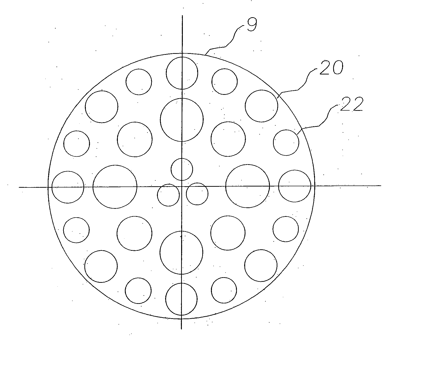
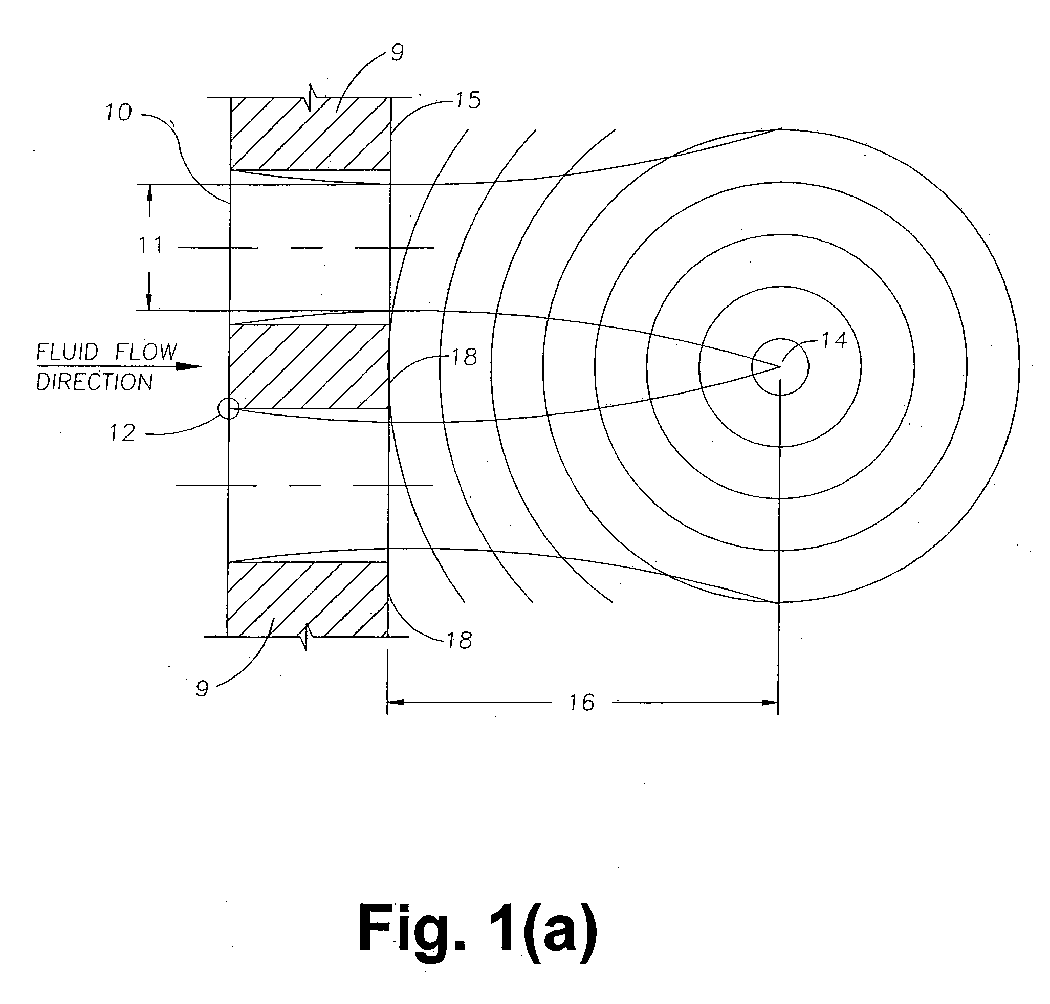
[0029] Referring now to FIG. 2(a), a perforated plate flow conditioner 9 includes a single central hole, an inner circular array of alternating large holes and smaller holes, and an outer circular array of alternating large holes and smaller holes. The difference between the diameters of the large and small holes in each circular array is preferably between 0.25% and 25% of the large hole diameter. In the preferred embodiment, the inner circular array contains eight holes, and the outer circular array contains sixteen holes. It is preferable to keep the hole size differences to a minimum to ensure the beneficial fluid flow properties of the flow conditioner are maintained. In an alternate embodiment, the arrays are rectangular or square.

[0030] Referring now to FIG. 2(b), the mismatching of the adjacent hole diameters causes the jetting of the fluid to not meet, thus not creating a coallesing point for sound to be generated.

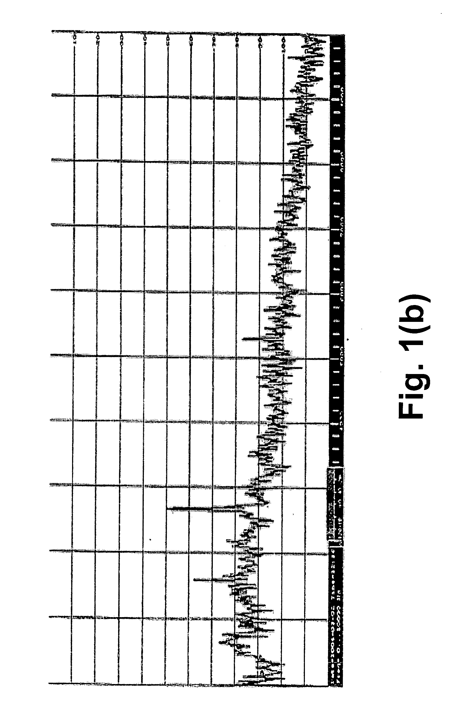
Operating Test Results

[0031] The graphs indicated in FIG...


PUM


Abstract

A perforated plate flow conditioner includes a central hole; and at least one outer array of alternating large outer holes and small outer holes, wherein the difference between the diameters of the holes in the array is between 0.25% and 25% of the large hole diameter. In an alternate embodiment, the conditioner further includes an inner array of alternating large inner holes and small inner holes, and wherein no two adjacent holes have the same diameter. In another alternate embodiment, the conditioner has no central hole, and has an array of alternatingly-sized holes.

Description

CROSS-REFERENCES TO RELATED APPLICATIONS [0001] This application is a continuation-in-part of, and claims the benefit of, pending application Ser. No. 10 / 936,832, which is incorporated herein by this reference.STATEMENT REGARDING FEDERALLY SPONSORED RESEARCH OF DEVELOPMENT [0002] Not applicable. FIELD OF THE INVENTION [0003] The present invention relates to pipeline perforated plate noise elimination generally, and in particular relates to the elimination of noise generated by the special application of a perforated plate flow conditioner to assist in flow measurement. BACKGROUND OF THE INVENTION [0004] Specially devised screens are used in the pipeline industry to reconfigure the fluid flow profile in the pipeline. When used to correct the fluid flow profile in the pipe they are referred to as perforated plate flow conditioners. An example of such a flow conditioner is the invention described in U.S. Pat. No. 5,762,107, which is incorporated herein by this reference. That patent di...

Claims


Application Information

Patent Timeline
Patent Type & Authority Applications(United States)
IPC IPC(8): F15D1/04F15D1/00F15D1/02F16K47/08F16K47/14
CPCF15D1/001F15D1/02F16K47/08F16K47/14G01F1/00G01F1/662
Inventor SAWCHUK, BLAINE DARENSAWCHUK, DALE PETER
Owner SAWCHUK BLAINE DAREN
Why Eureka
Try Eureka