
External mix air assisted spray nozzle assembly

Inactive Publication Date: 2006-05-11
SPRAYING SYST
View PDF6 Cites 19 Cited by
  • Summary
  • Abstract
  • Description
  • Claims
  • Application Information

AI Technical Summary

Benefits of technology

[0006] It is an object of the present invention to provide an external mix air atomizing spray nozzle assembly which is adapted for more efficient and reliable operation.
[0007] Another object is to provide an external mix air atomizing spray nozzle assembly as characterized above which is operable with less likelihood of spray material build up on the face of the air cap or in and around the pressurized air discharge orifices.
[0008] A further object is to provide a spray nozzle assembly of the above kind that is relatively simple in design and lends itself to economical manufacture.

Problems solved by technology

Because atomization occurs externally of the liquid discharge orifice, the intermixing liquid and air streams can be susceptible to control and performance problems.
While this form of air cap performs well with many materials, in spraying materials that are prone to build up, the protruding ears can be problem prone.
Liquid forcefully atomized downstream of the liquid discharge orifice can cause random spray to collect on the ears and on the face of the air cap, resulting in a build up that eventually interferes with performance of the nozzle.
This arrangement can further cause build up of solid material onto the exposed surfaces of the air cap.
Indeed, liquid particles drawn radially outwardly by a low pressure area created by the atomizing air discharging from the central annular air passages about the nose can cause overspray to be deposited onto the face of the air cap surrounding the central annular air passage.
This build up also can eventually interfere with the spray nozzle performance, and in some cases, block the atomizing air completely.

Method used


Image

  • External mix air assisted spray nozzle assembly
  • External mix air assisted spray nozzle assembly
  • External mix air assisted spray nozzle assembly

Examples


Embodiment Construction

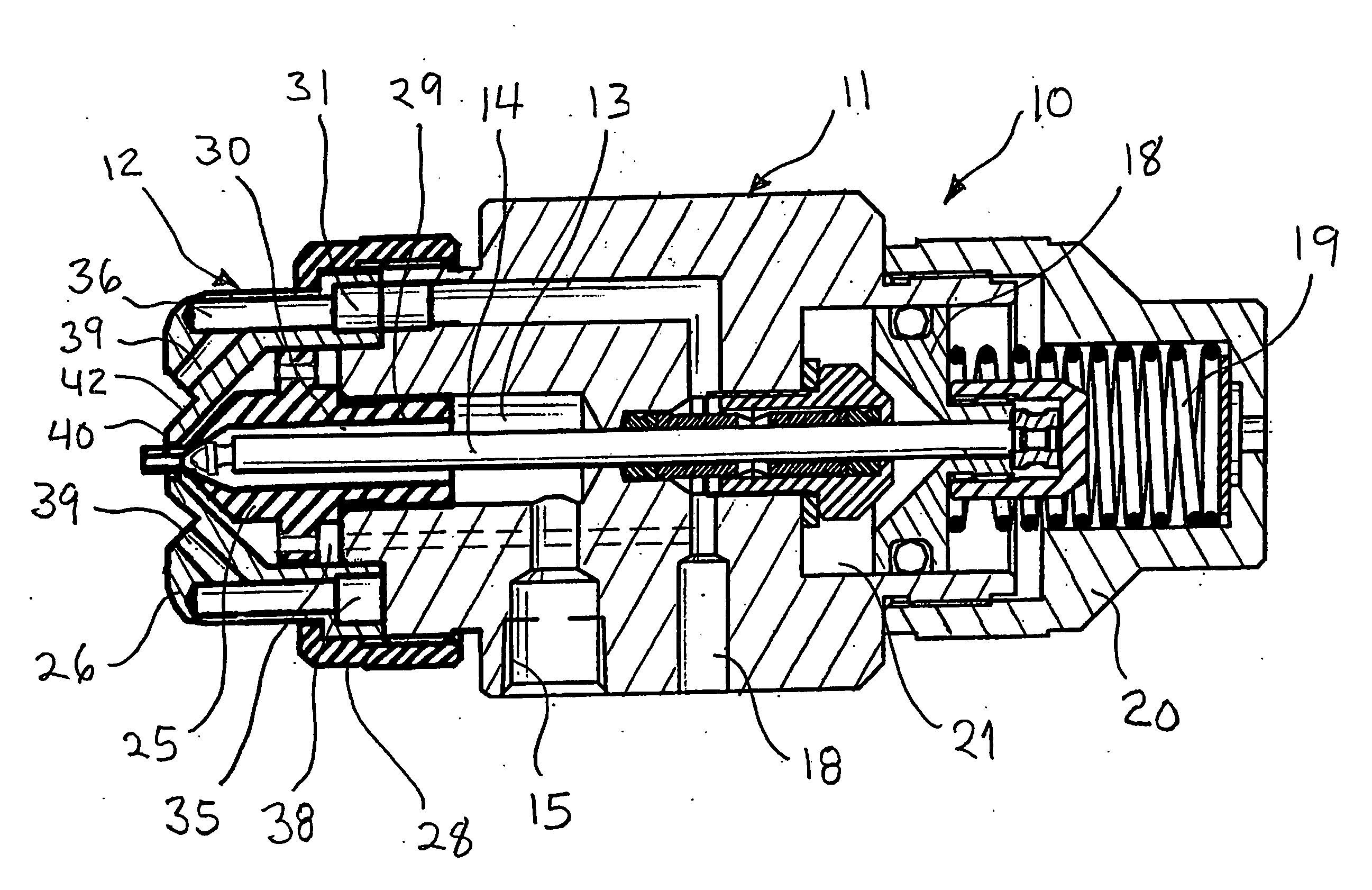
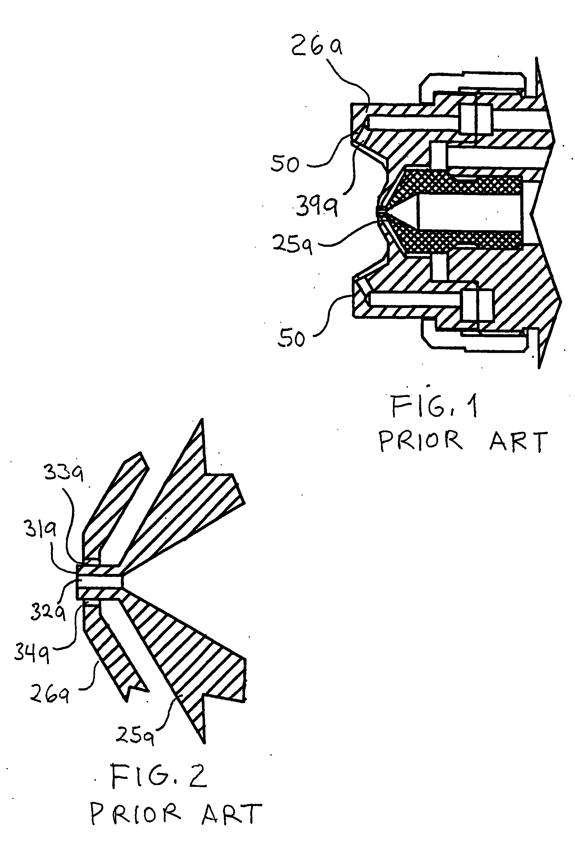
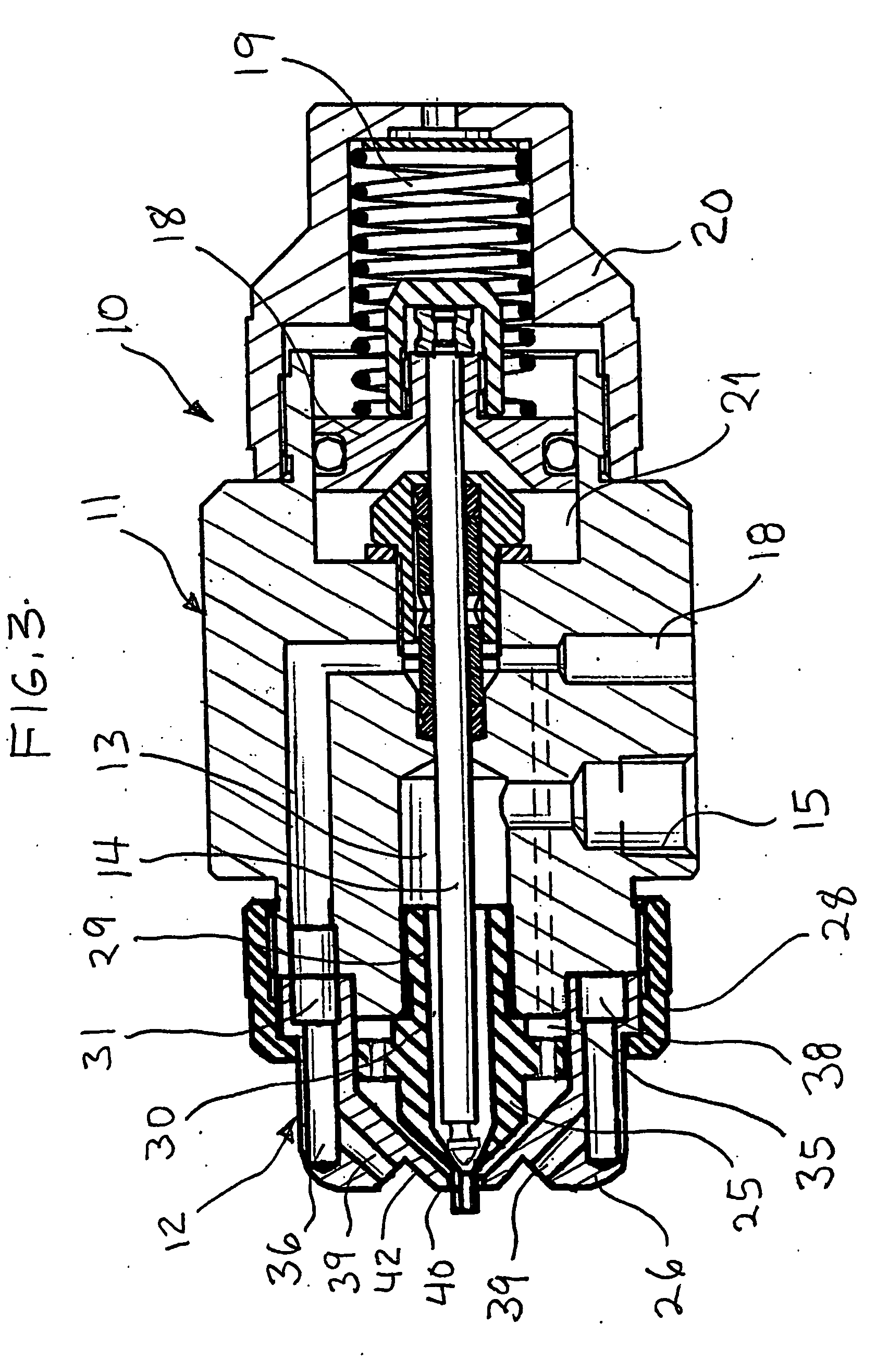
[0017] Referring now more particularly to FIG. 3 of the drawings, there is shown an illustrative air atomizing liquid spray device 10 comprising a spray gun body 11 having an external mix air assisted spray nozzle assembly 12 in accordance with the invention at a downstream end. The spray device 10 in this instance has a reciprocatable valve needle 13 for controlling discharging liquid spray for the nozzle assembly 12. The basic structure and mode of operation of the spray device are known in the art, for example, as shown in the aforementioned U.S. Pat. No. 5,707,010 and U.S. application Ser. No. 09 / 892,138, the disclosures of which are incorporated herein by reference. The overall structure and mode of operation of the spray device should be understood to be illustrative of only one example of a spray device with which the nozzle assembly of the present invention may be used.

[0018] The illustrated spray gun body 11 axially supports the valve shut-off needle 14 within an axial liq...


PUM


Abstract

A spray device comprising a body having a liquid discharge passage and a spray nozzle assembly affixed to the body is provided. The spray nozzle assembly includes a liquid spray tip for directing liquid from the liquid passage in the body into a predetermined spray pattern and an atomizing fluid cap. The liquid spray tip includes a forwardly extending nose portion that defines a liquid discharge orifice. The nose extends through a central opening in the air cap thereby defining an annular atomizing fluid discharge orifice that communicates with an atomizing fluid inlet. The nose extends in a downstream direction past the central opening in the air cap such that the liquid discharge orifice is arranged at least approximately 2 mm. downstream of the annular atomizing fluid discharge orifice.

Description

FIELD OF THE INVENTON [0001] The present invention relates generally to spray nozzle assemblies, and more particularly, to external mix air atomizing spray nozzle assemblies in which a discharging liquid flow stream is atomized and formed into the desired spray pattern by pressurized air externally of the liquid discharge orifice. BACKGROUND OF THE INVENTION [0002] External mix air atomizing spray nozzles are known for their ability to control liquid particle size and spray distribution by pressurized air, independent of liquid flow rate. They also can be used with relatively low pressure air supplies which can be generated by inexpensive blowers, rather than air compressors. Because atomization occurs externally of the liquid discharge orifice, the intermixing liquid and air streams can be susceptible to control and performance problems. [0003] Conventional external mix spray nozzle assemblies, such as depicted in FIGS. 1 and 2, commonly comprise a nozzle body or spray tip 25a havi...

Claims


Application Information

Patent Timeline
IPC IPC(8): B05B1/28B05B7/06B05B7/08B05B7/12
CPCB05B7/066B05B7/0815B05B7/1254B05B7/1272
Inventor HUFFMAN, DAVIDC
Owner SPRAYING SYST
Learn More