Systems and methods for detecting inkjet defects

a technology of inkjet image and defect detection, applied in the field of systems and methods for inkjet image defect detection, can solve the problems of inkjet defect detection inkjet defect detection with an iod as a standalone procedure, and inkjet defect detection without the most efficient system solution, so as to save time, ink and other precious system resources, and reduce wasted system resources.

Active Publication Date: 2006-05-11
XEROX CORP
View PDF40 Cites 18 Cited by
  • Summary
  • Abstract
  • Description
  • Claims
  • Application Information

AI Technical Summary

Benefits of technology

[0012] Thus, in order to further conserve time, ink, and other precious system resources, U.S. Patent Application [Attorney Docket No. 119519] proposes systems and methods that incorporate the marking of test images onto blank portions of the intermediate substrate, other than the inter-document zones within a standard print cycle, thereby reducing wasted system resources. U.S. Patent Application [Attorney Docket No. 119519] is incorporated herein by reference in its entirety.

Problems solved by technology

As discussed above, inkjets within an inkjet image reproduction device may become defective as the marking intensity attributes (e.g. drop mass, drop velocity, directionality, etc.) drift with time.
Inkjet defects are typically caused by an amount of marking material clogging or partially clogging the defective inkjet.
However, simply providing basic inkjet defect detection with an IOD as a standalone procedure does not provide the most efficient systems solution since the inkjet defect detection procedure takes time, consumes ink, and utilizes other precious systems resources if invoked too often.
Basic inkjet defect detection with an IOD as a standalone procedure does not provide the most efficient systems solution because the timing and drum size in a multi-pass inkjet device are generally configured so that all regions in an inter-document zone on an intermediate substrate come into contact with the transfer roller.
As a result, system resources that are dedicated to the independent test cycle are wasted (i.e., cannot be utilized for print cycles).

Method used


Image

  • Systems and methods for detecting inkjet defects
  • Systems and methods for detecting inkjet defects
  • Systems and methods for detecting inkjet defects

Examples


Embodiment Construction

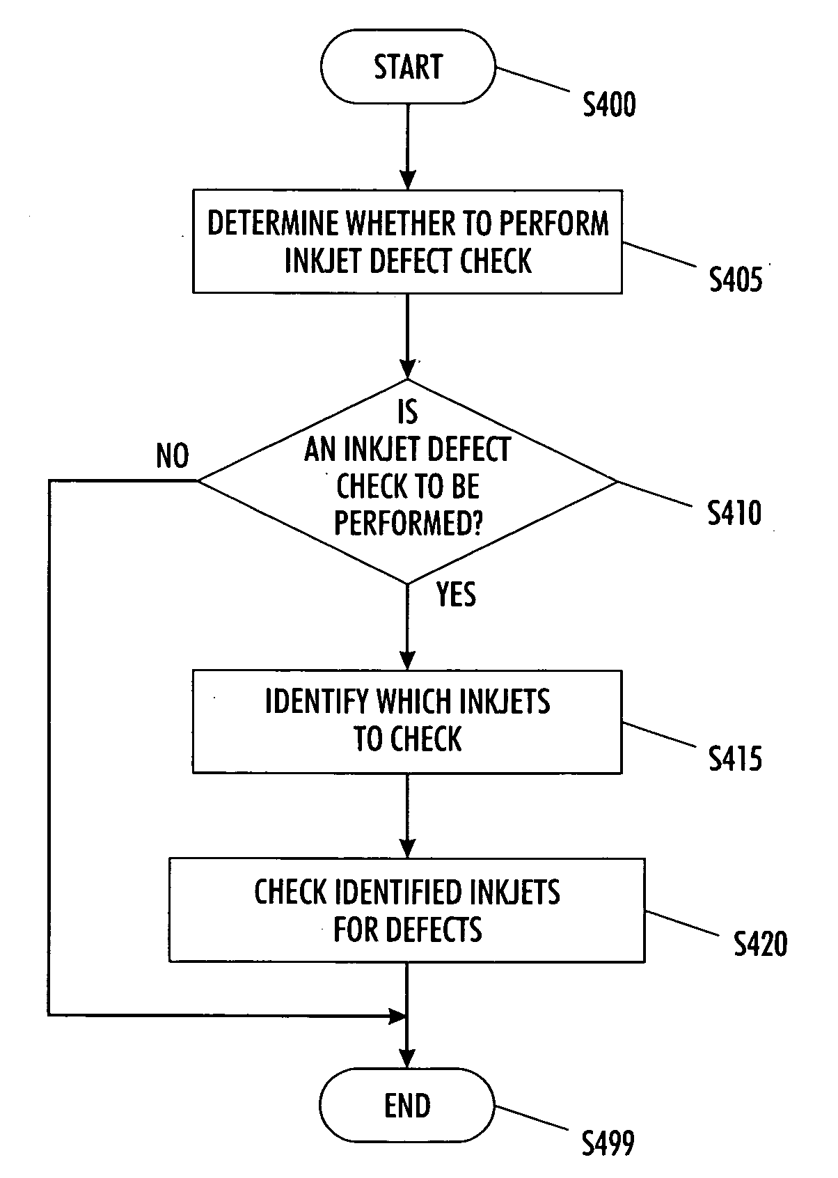
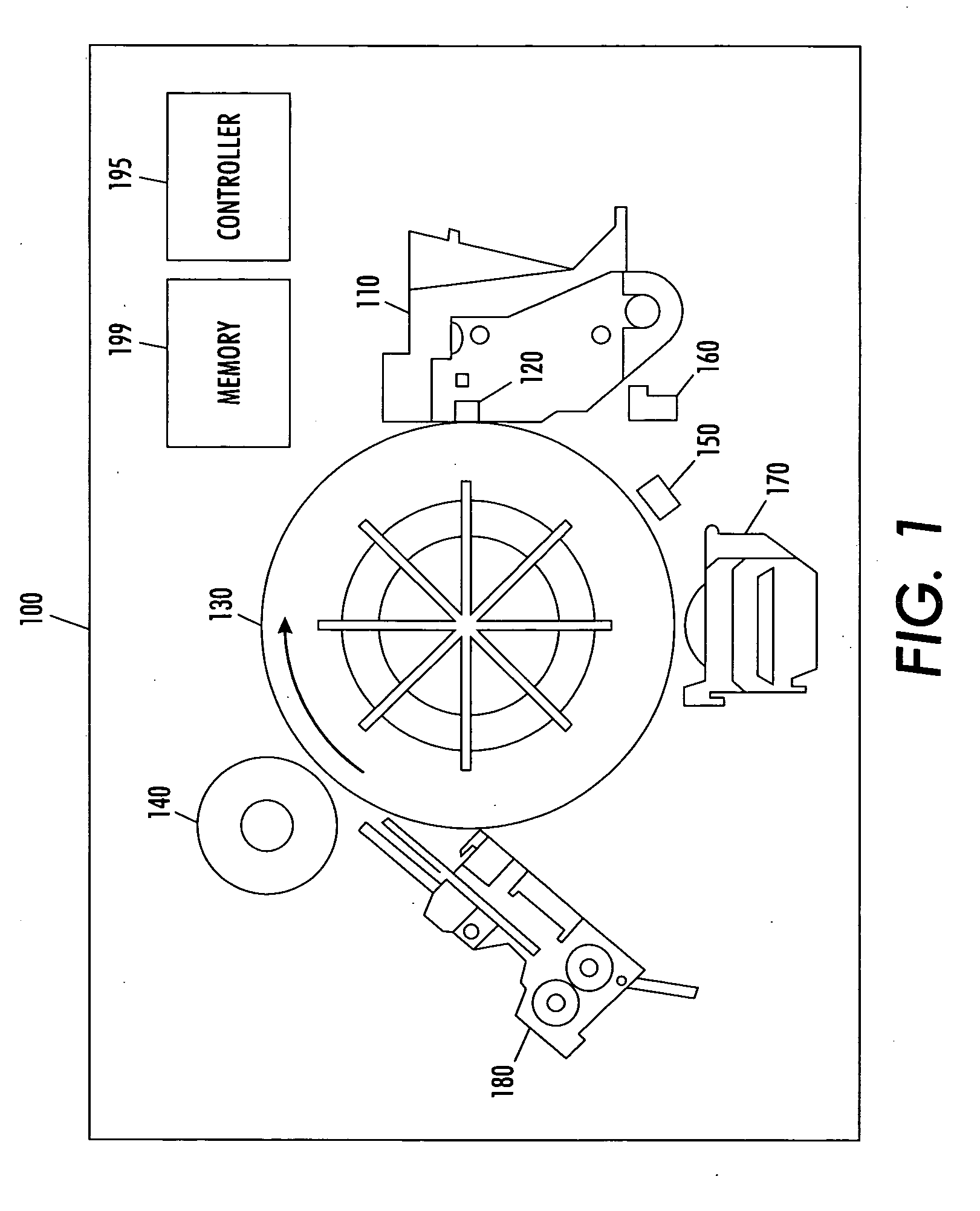
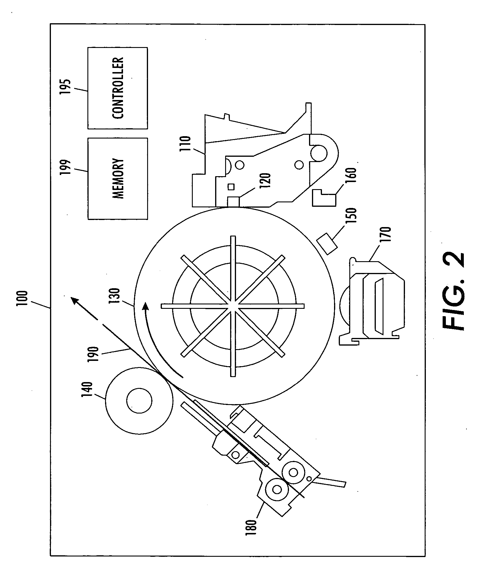
[0029] For a general understanding of an inkjet device, such as, for example, a solid inkjet printer, an ink-jet printer, or an inkjet facsimile machine, in which the features of this invention may be incorporated, reference is made to FIGS. 1-3. Although the various exemplary embodiments of this invention for detecting inkjet defects are particularly well adapted for use in such a machine, it should be appreciated that the following exemplary embodiments are merely illustrative. Rather, aspects of various exemplary embodiments of this invention may be achieved in any media feed mechanism and / or image reproduction device containing at least one print head with inkjets intended to transfer an image onto an intermediate image substrate.

[0030] As shown in FIG. 1, the exemplary inkjet device 100 includes, in part, a print head 110, one or more inkjets 120, an intermediate transfer substrate (intermediate transfer drum 130), a transfer roller 140, an image sensor 150, a print head maint...


PUM


Abstract

A method for testing inkjets for defects in an inkjet device includes determining, based on the likelihood that one or more inkjets are defective, whether to perform an inkjet defect test, The method may also include, identifying, if it is determined to perform an inkjet defect test, which inkjets to test based on properties of the inkjets, the number of identified inkjets being less than a total number of inkjets in the inkjet device; and testing the identified inkjets for defects using an image sensor.

Description

BACKGROUND OF THE INVENTION [0001] 1. Field of Invention [0002] This invention relates to systems and methods for inkjet defect detection. [0003] 2. Description of Related Art [0004] There exists printers wherein and inkjet print head moves relative to and ejects marking material toward an intermediate substrate in order to form an image on the intermediate substrate. The inkjet print head includes a number of individual inkjets that each ejects an amount of marking material. Subsequently, the image is transferred from the intermediate substrate onto a sheet of media. The quality of the image formed on the sheet of media is influenced by, among other things, the ability of the individual inkjets to consistently eject ink. [0005] Solid inkjet print heads are prone to develop defects such as clogged inkjets. For example, inkjets within the print head can become clogged such that ink is not consistently ejected. Once an inkjet becomes defective, it will remain defective until the defec...

Claims


Application Information

Patent Timeline
Patent Type & Authority Applications(United States)
IPC IPC(8): H04N1/46
CPCB41J2/16579B41J2/015Y10S707/99953
Inventor EKLUND, ELLIOTT A.FOLKINS, JEFFREY J.KNIERIM, DAVID L.
Owner XEROX CORP
Why Eureka
Try Eureka