Variable-length coding device and method of the same

a coding device and variable-length technology, applied in signal generators with optical-mechanical scanning, color television with bandwidth reduction, signal systems, etc., can solve the problems of low resolution and difficulty in uniquely determining offsets, and achieve the effect of improving coding efficiency

Inactive Publication Date: 2006-05-11
KK TOSHIBA
View PDF1 Cites 74 Cited by
  • Summary
  • Abstract
  • Description
  • Claims
  • Application Information

AI Technical Summary

Benefits of technology

[0012] According to embodiments of the present invention, the parameter for qu

Problems solved by technology

However, the integer orthogonal transformation coefficient is not necessarily approximated to the Laplace distribution in sequence units or macro block units, and it is difficult to uniquely determine the offset.
However, there is a problem that

Method used


Image

  • Variable-length coding device and method of the same
  • Variable-length coding device and method of the same
  • Variable-length coding device and method of the same

Examples


first embodiment

(1) Processing Content of Moving Image Coding Device

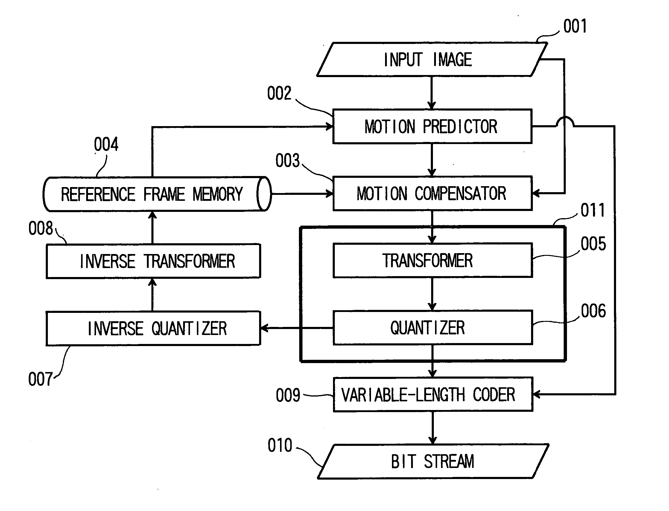
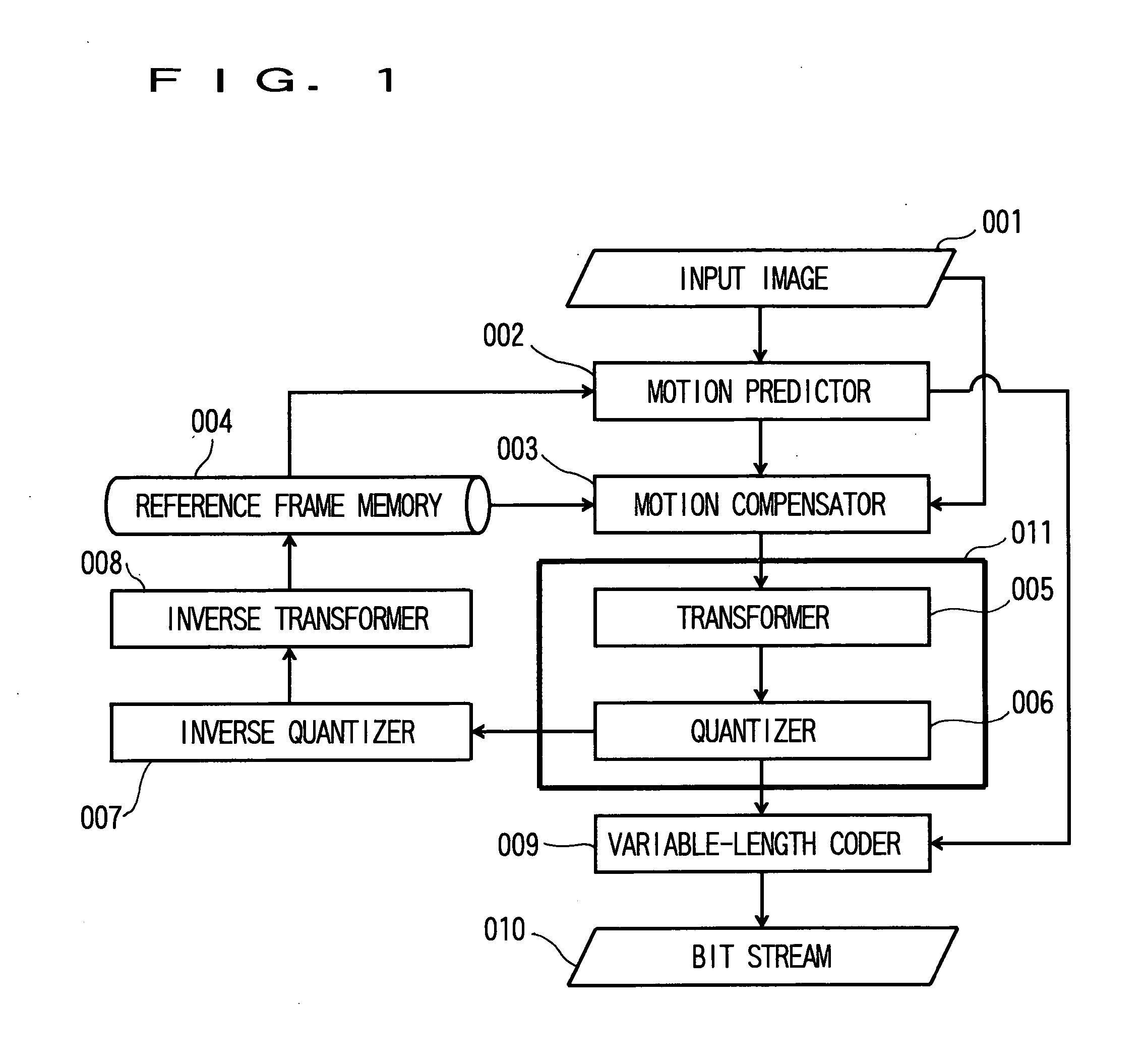
[0023]FIG. 1 is a view schematically showing a processing flow of a moving image coding device according to a first embodiment of the invention. This moving image coding device adopts, for example, H.264. Incidentally, also in MPEG-1 / 2 / 4 and H.261 / 262 / 263 standardized by ISO or ITU-T, the coding processing is performed by a similar processing flow.

[0024] An input image 001 is inputted to a motion predictor 002 and a motion compensator 003.

[0025] In the motion predictor 002, motion vector detection is performed, and in the motion compensator 003, motion compensation is performed from the detected motion vector, and a residual signal relative to the input image is obtained.

[0026] The residual signal is transformed by a transformer 005, and is then quantized by a quantizer 006. This quantization processing will be described later in detail.

[0027] A transformation coefficient after the quantization and the motion vector detected ...

second embodiment

[0071] A second embodiment relating to a calculation method for the generated code amount R and the quantization distortion amount D is a method in which a calculating cost for coding is reduced.

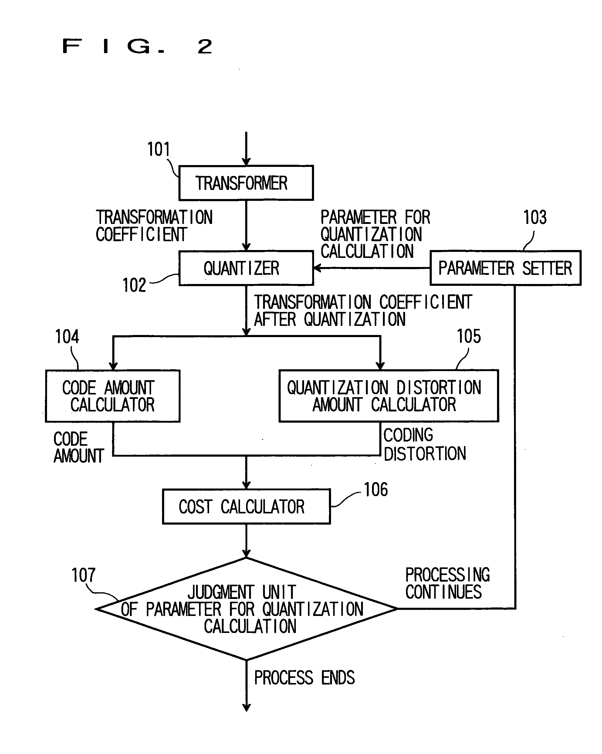
[0072] A block 304 shown in FIG. 4 is the code amount calculator 104 in FIG. 2, and a block 305 shown in FIG. 4 is the quantization distortion amount calculator 105 in FIG. 2.

[0073] Since the calculating cost is increased when the generated code amount R and the quantization distortion amount D are accurately calculated, with respect to the generated code amount, in this embodiment, a method disclosed in Japanese Patent Application No. 2004-96763 is adopted in which rate distortion optimization based on the Lagrange s method of undetermined multipliers is realized at low calculating cost.

[0074] A transformation coefficient counter 306 is provided in the inside of the code amount calculator 304, and counts a value of a nonzero coefficient of the transformation coefficients after the quanti...

modified example

[0077] The invention is not limited to the above embodiments, but may be variously modified within the scope of its gist. Besides, various modifications or improvements can be added to the above embodiments.

[0078] For example, although H.264 is adopted in the embodiments, not to mention moving images of MPEG-1 / 2 / 4, even in the case where JPEG or JPEG2000 of still images is used, a similar effect can be obtained. The invention is not limited to H.264, but can be applied to systems of sound and others in addition to systems of only images, that is, all systems requiring quantization.

[0079] Besides, the description has been made especially with respect to the residual signal 4×4 in the quantization of H.264, the invention can be similarly applied to DC color difference 2×2, DC brightness 4×4, or residual signal 8×8.


PUM


Abstract

It is an object to improve coding efficiency by suitably setting, with respect to input information in moving image coding, a parameter for quantization calculation at the time of quantization. Various parameters for quantization calculation are set by a parameter setter 103, quantization is performed with the set parameters for quantization calculation by a quantizer 102, a coding cost J is calculated from a generated code amount R and a quantization distortion amount R obtained as a result thereof, and a parameter judgment unit 107 for quantization calculation selects, as a parameter for quantization calculation having highest coding efficiency, a parameter by which the coding cost J becomes minimum.

Description

CROSS-REFERENCE TO RELATED APPLICATIONS [0001] This application is based upon and claims the benefit of priority from the prior Japanese Patent Application No. 2004-324211, filed on 8 Nov. 2004; the entire contents of which are incorporated herein by reference. TECHNICAL FIELD [0002] The present invention relates to a variable-length coding device for realizing variable-length coding of a high quality moving image. BACKGROUND OF THE INVENTION [0003] As a moving image coding technique, an MPEG (Moving Picture Experts Group) system has been put to practical use. The MPEG system is based on motion compensative prediction, orthogonal transformation and variable-length coding. A residual signal relative to an original image is acquired by the motion compensative prediction, and the residual signal is orthogonally transformed to obtain a transformation coefficient. The transformation coefficient is quantized by a quantization scale corresponding to a target bit rate, and the transformatio...

Claims


Application Information

Patent Timeline
IPC IPC(8): H04N11/04H04N7/12H04B1/66H04N11/02
CPCH04N19/176H04N19/147H04N19/172H04N19/15H04N19/48H04N19/126H04N19/18H04N19/177H04N19/19H04N19/61
Inventor MATSUMURA, ATSUSHICHUJOH, TAKESHIKOTO, SHINICHIRO
Owner KK TOSHIBA
Why Eureka
Try Eureka