Imaging device and image processing program for estimating fixed pattern noise from partial noise output of available pixel area

a technology of image processing and fixed pattern noise, which is applied in the field of image processing, can solve the problems of reducing affecting the continuous shooting speed, and noticeably lowering the speed of continuous shooting of electronic cameras, so as to shorten the time required for a photographing sequence

Active Publication Date: 2006-05-11
NIKON CORP
View PDF9 Cites 189 Cited by
  • Summary
  • Abstract
  • Description
  • Claims
  • Application Information

AI Technical Summary

Benefits of technology

[0012] In view of the above-described problems, it is an object of the present invention to provide an effective fixed pattern noise eliminating technique for shortening the time required for a photographing sequence.

Problems solved by technology

This causes a problem in continuous shooting that the speed of continuous shooting is lowered by the time corresponding to this read time of the fixed pattern noise.
Accordingly, the buffer memory becomes fully occupied in a short time, causing the delay of the continuous shooting speed.
Due to such double causes, the elimination of the fixed pattern noise leads to a problem of noticeably lowering the speed of the continuous shooting of an electronic camera.
Meanwhile, in the case of eliminating the fixed pattern noise with a computer or the like at a later time, the fixed pattern noise for one screen has to be stored in addition to captured images in an image recording medium (a memory card or the like), which will accordingly cause a problem of reduction in the number of frames recordable in the memory card or the like.

Method used


Image

  • Imaging device and image processing program for estimating fixed pattern noise from partial noise output of available pixel area
  • Imaging device and image processing program for estimating fixed pattern noise from partial noise output of available pixel area
  • Imaging device and image processing program for estimating fixed pattern noise from partial noise output of available pixel area

Examples


first embodiment

[Configuration Description of First Embodiment]

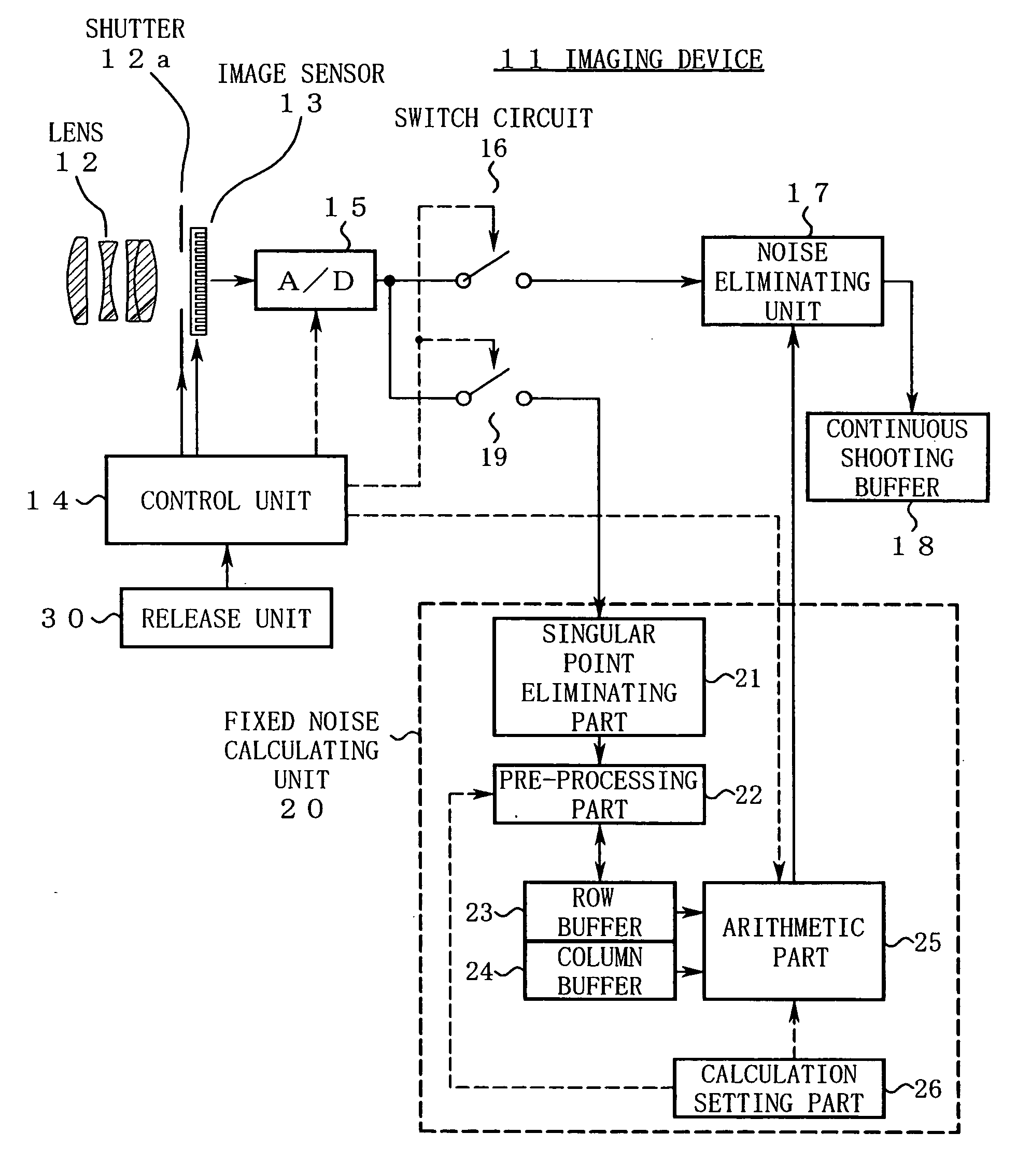
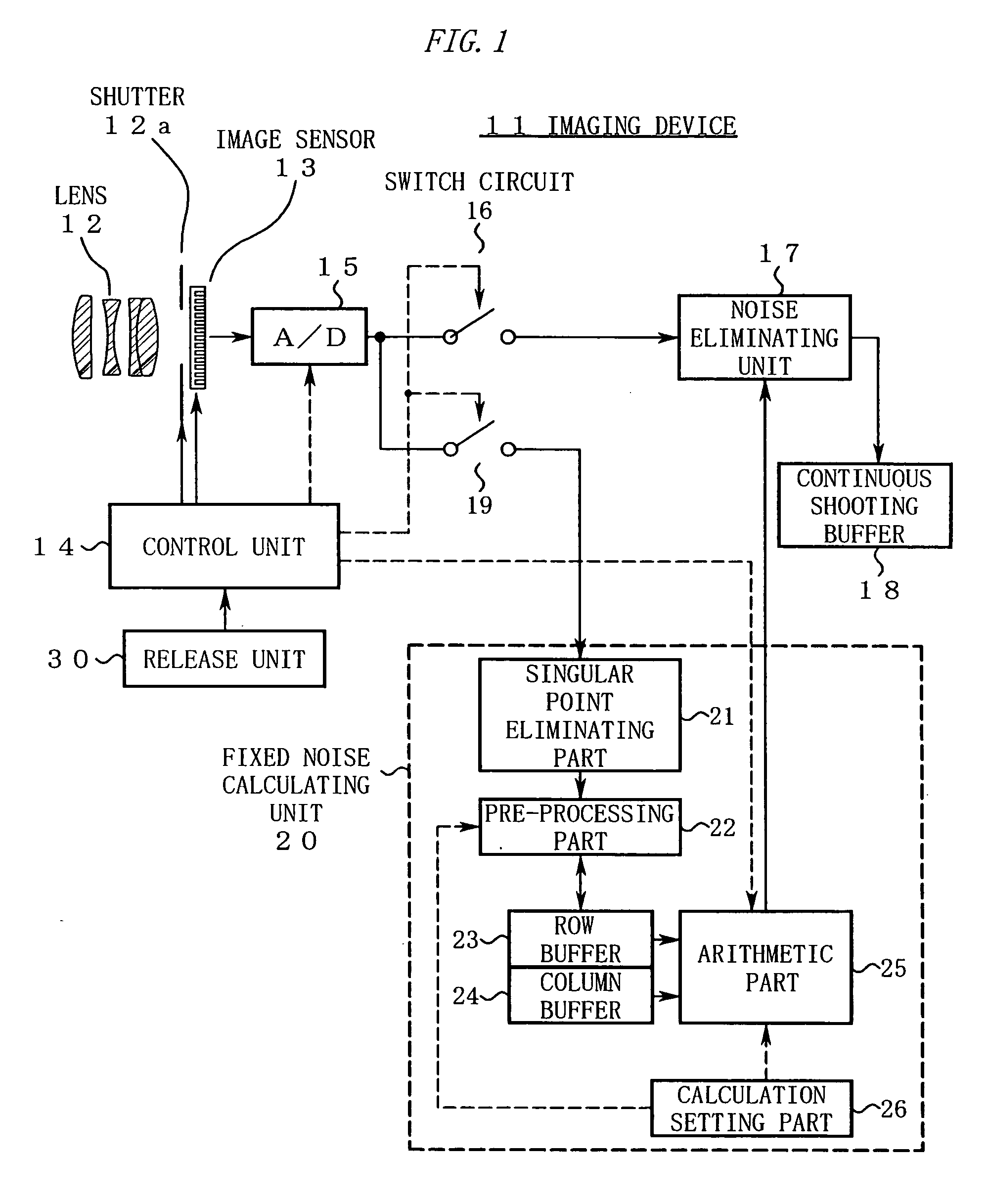
[0040]FIG. 1 is a diagram showing a configuration of an imaging device 11 in a first embodiment.

[0041] In FIG. 1, a lens 12 is attached to the imaging device 11. A shutter 12a and an image sensor 13 are disposed in an image space of the lens 12. A control unit 14 receives a photographing instruction from a release unit 30. In response to this photographing instruction, the control unit 14 performs a control operation so as to drive the shutter 12a and the image sensor 13 and reads from the image sensor 13“a noise output obtained from a partial area (a predetermined row, a predetermined column, or the like) of an available pixel area” and “image data for one screen”.

[0042] A signal thus outputted from the image sensor 13 is inputted to a switch circuit 16 and a switch circuit 19 after being converted to a digital signal in an A / D converting unit 15. The control unit 14 performs changeover control of these switch circuits 16, 19 to div...

second embodiment

[0094]FIG. 7 is a diagram showing a configuration of an imaging device 11a in a second embodiment.

[0095] The imaging device 11a is structurally characterized in that the column buffer 24 in the configuration of the first embodiment (FIG. 1) need not be provided. The other configuration is the same as that of the first embodiment (FIG. 1, FIG. 2), and therefore, description of the configuration will be omitted here.

[0096]FIG. 8 is a timing chart illustrating operations of the second embodiment.

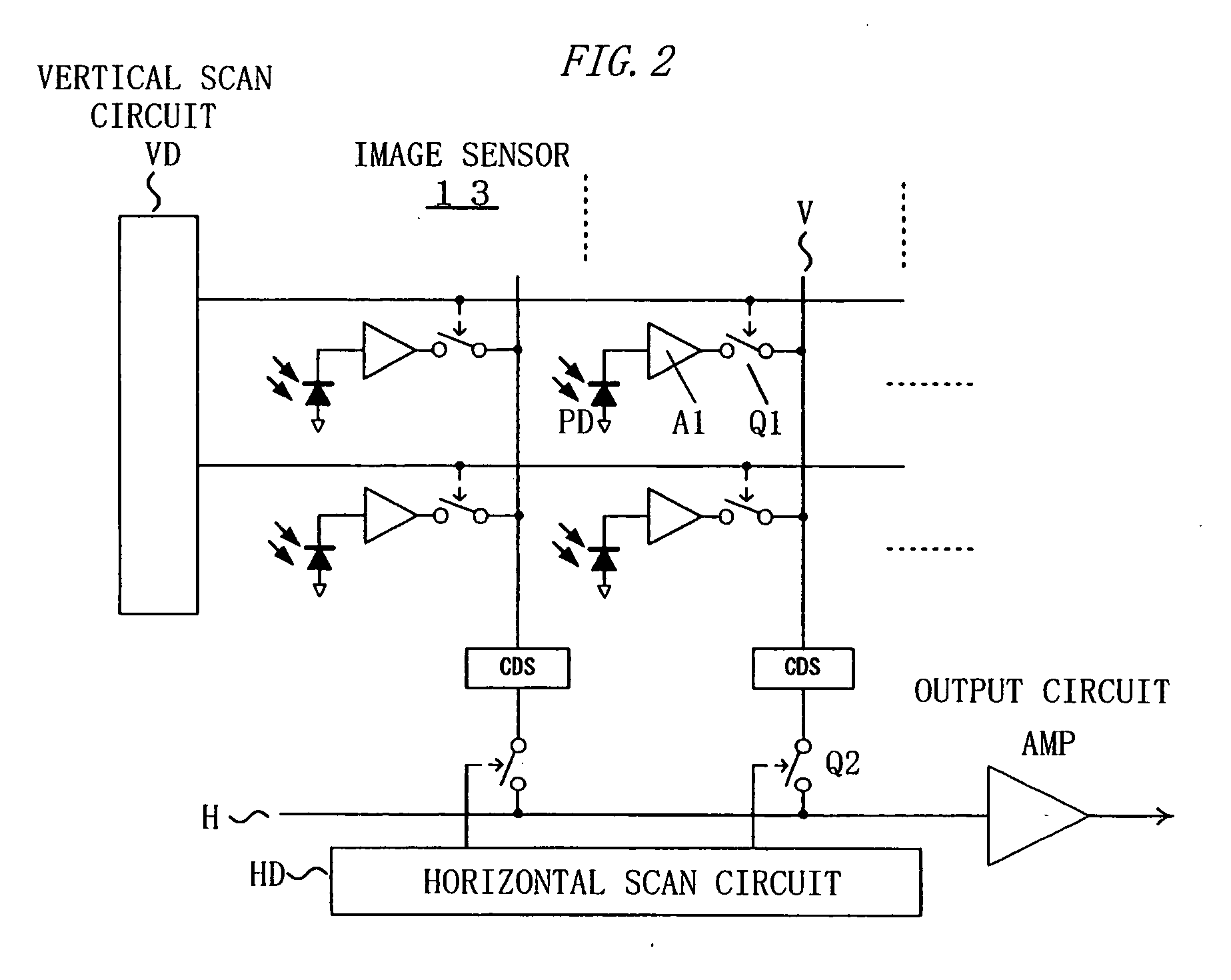
[0097] Hereinafter, the operations of the second embodiment will be described in the order of the step number shown in FIG. 8. [0098] Step S11: A user gives a photographing instruction to a control unit 14 by operating a release unit 30. [0099] Step S12: The control unit 14 drives a vertical scan circuit VD and a horizontal scan circuit HD in an image sensor 13 while keeping a shutter 12a closed, and selectively reads noise outputs (dark outputs of photodiodes PD) of predetermined rows shown ...


PUM


Abstract

An imaging device of the present invention includes an image capturing unit, a noise obtaining unit, a fixed noise calculating unit, and a noise eliminating unit. The image capturing unit generates image data by photoelectrically converting, pixel by pixel, a subject image formed on an available pixel area of a light-receiving surface. The noise obtaining unit reads a noise output from a partial area of the available pixel area. The fixed noise calculating unit calculates an estimation of fixed pattern noise of the available pixel area based on the noise output read from the partial area. The noise eliminating unit subtracts the fixed pattern noise from the image data.

Description

CROSS REFERENCE TO RELATED APPLICATION [0001] This application is based upon and claims the benefit of priority from Japanese Patent Application No. 2004-308621, filed on Oct. 22, 2004, the entire contents of which are incorporated herein by reference. BACKGROUND OF THE INVENTION [0002] 1. Field of the Invention [0003] The present invention relates to an imaging device that reduces fixed pattern noise from captured image data. [0004] The present invention also relates to an imaging device that records information on the fixed pattern noise together with the image data and to an image processing program for reducing the fixed pattern noise from the image data by computer processing. [0005] 2. Description of the Related Art [0006] Image quality of an imaging device is generally lowered when fixed pattern noise is superimposed on image data. A conventional method improves the image quality by storing the fixed pattern noise for one screen read from an image sensor and eliminating the f...

Claims


Application Information

Patent Timeline
Patent Type & Authority Applications(United States)
IPC IPC(8): G06K9/40H04N5/232H04N5/335H04N5/365H04N5/369H04N5/374H04N5/376H04N101/00
CPCH04N5/3651H04N25/671
Inventor MORISHITA, AKIHIKO
Owner NIKON CORP
Why Eureka
Try Eureka