

Image capture device
a technology of image blur and capture device, which is applied in the field of image capture device, can solve the problems of inability to make and difficulty in making proper compensation for image blur
- Summary
- Abstract
- Description
- Claims
- Application Information
AI Technical Summary
Benefits of technology
Problems solved by technology
Method used
Image

Examples
first embodiment
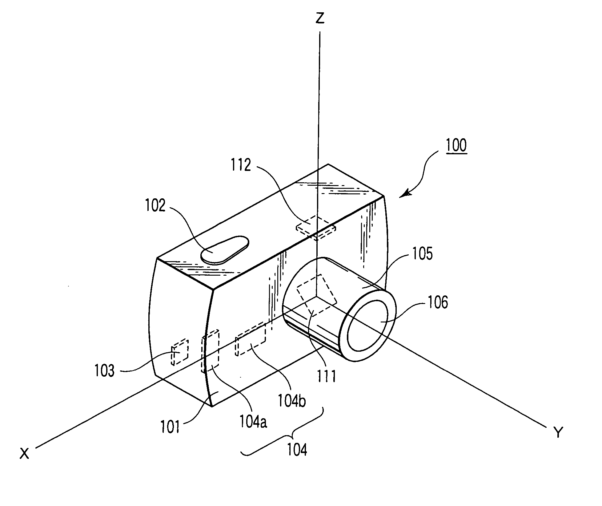
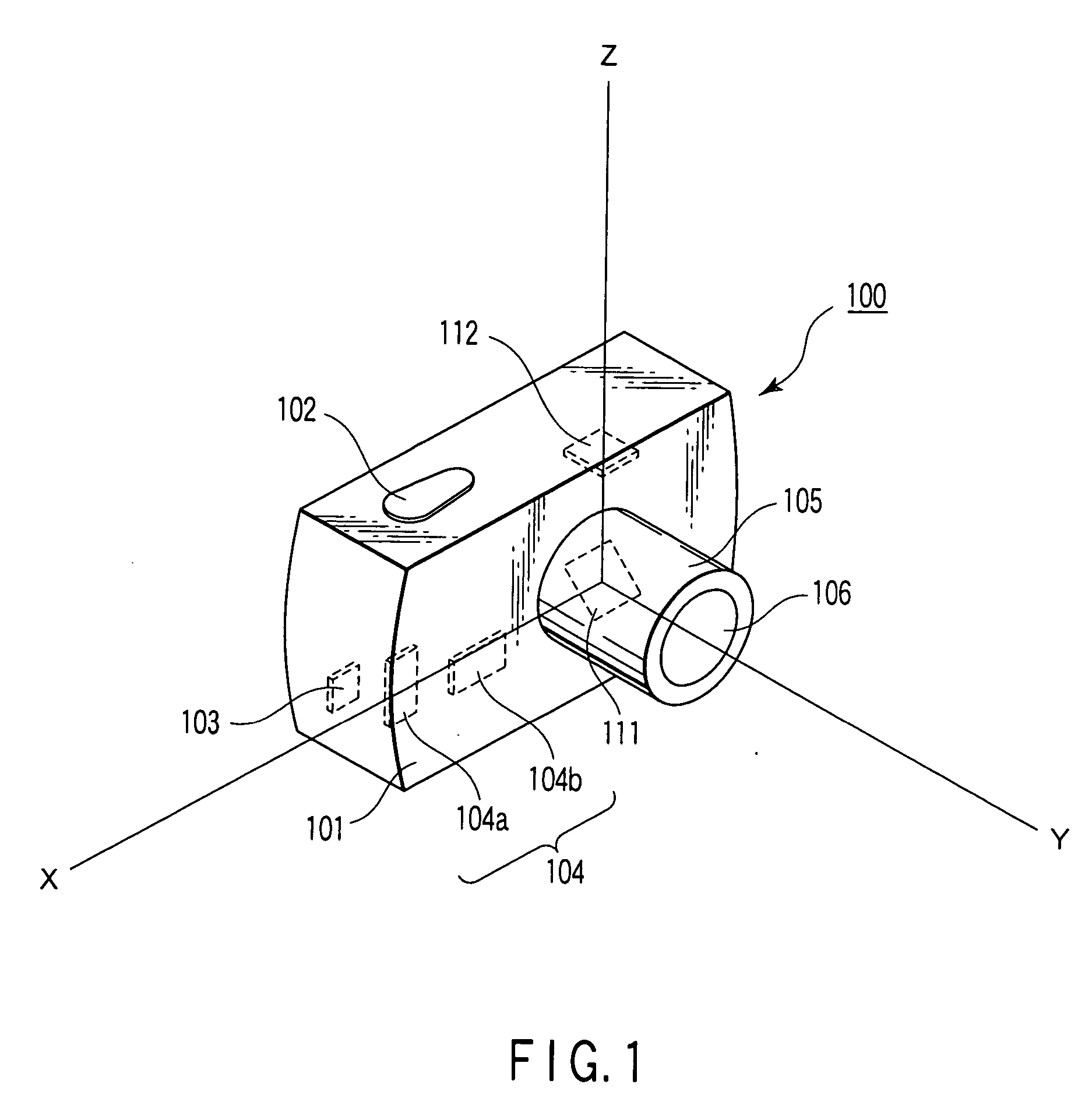
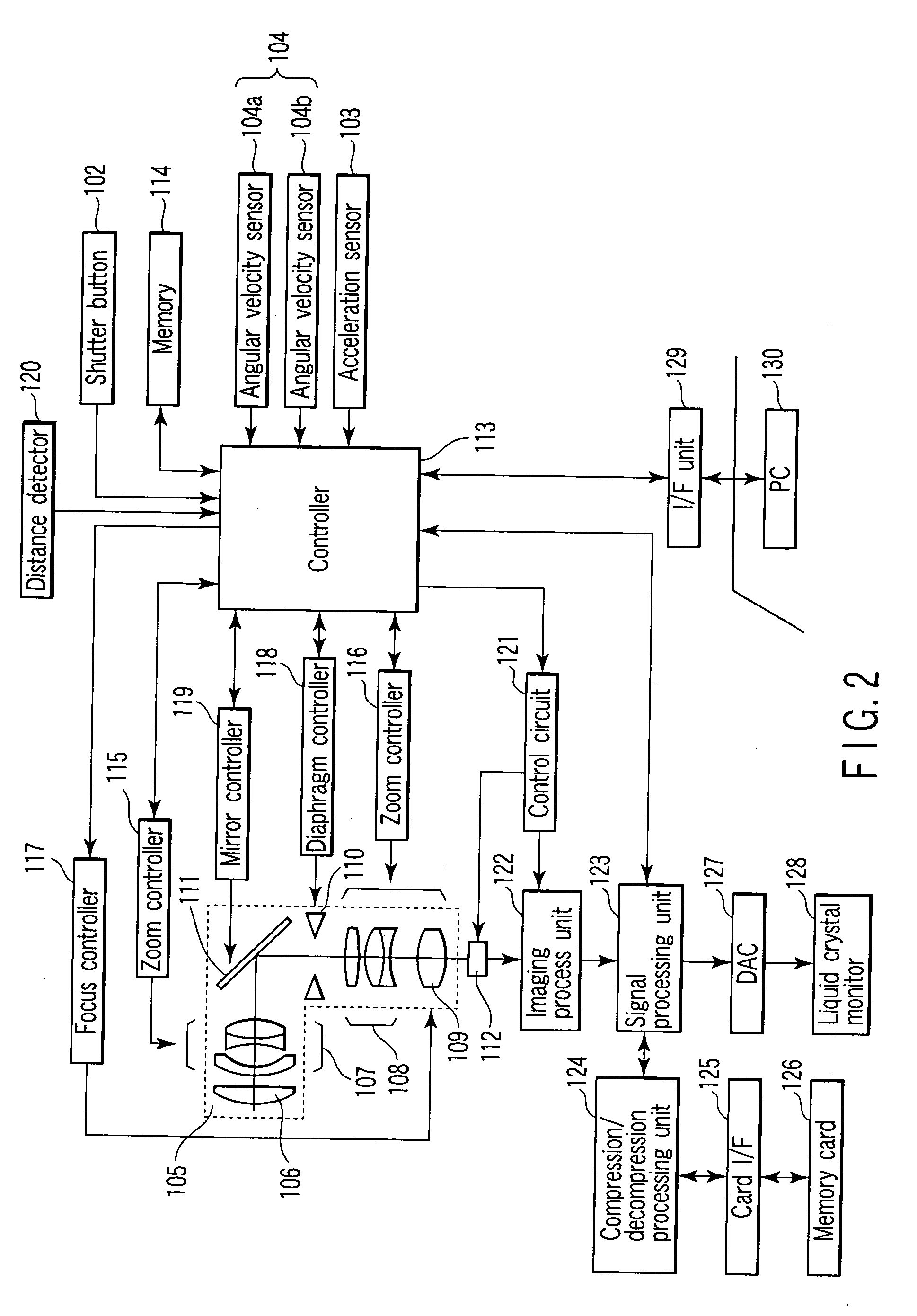
[0024]FIG. 1 is a schematic perspective view illustrating the exterior structure of a digital camera (image capture device) according to a first embodiment of the present invention and FIG. 2 is a block diagram of the digital camera of the first embodiment.
[0025] The digital camera 100 is provided on the top of its main body 101 with a shutter button 102 adapted to instruct the commencement of shooting. Inside the main body 101 are provided a three-axis acceleration sensor 103 adapted to detect the translational component of motion and an angular velocity sensor 104 (composed of sensors 104a and 104b) adapted to detect the rotational component of the motion.
[0026] Inside a lens barrel module 105 are provided a first lens group 106, a second lens group 107, a third lens group 108, a fourth lens group 109, a diaphragm 110, and a variable mirror 111. A subject image passes through the first and second lens groups 106 and 107, then is reflected by the variable mirror 111 into the thir...
second embodiment
[0051]FIG. 6 is a schematic perspective view of a digital camera (image capture device) according to a second embodiment. FIG. 7 is a block diagram of the digital camera of the second embodiment. Since the basic configuration of this embodiment is the same as that of the first embodiment, corresponding parts to those in the first embodiment are denoted by like reference numerals and detailed descriptions thereof are omitted. Many matters described in the first embodiment apply to this embodiment as well and hence descriptions thereof are also omitted.
[0052] This embodiment is equipped with three-axis acceleration sensors 103a and 103b. Also, an adder 140 is provided by which the output signals of the three-axis acceleration sensors 103a and 103b are added together. The three-axis acceleration sensors 103a and 103b have the same characteristics.
[0053] As shown in FIG. 6, suppose that, with the center of the variable mirror 111 set at the origin, the optical axis directed from the c...
third embodiment
[0059]FIG. 9 is a schematic perspective view of a digital camera (image capture device) according to a third embodiment. FIG. 10 is a block diagram of the digital camera of the third embodiment. Since the basic configuration of this embodiment is the same as that of the first embodiment, corresponding parts to those in the first embodiment are denoted by like reference numerals and detailed descriptions thereof are omitted. Many matters described in the first embodiment apply to this embodiment as well and hence descriptions thereof are also omitted.
[0060] This embodiment is equipped with three-axis acceleration sensors 103a and 103b. A shutter button 102a is provided in the vicinity of the three-axis acceleration sensor 103a and a shutter button 102b is provided in the vicinity of the three-axis acceleration sensor 103b.
[0061] In a state where the shutter button 102a or 102b has been depressed halfway, the controller 113 makes a decision of which of the shutter buttons 102a and 1...
PUM
 Abstract
Description
Claims
Application Information