Fluid control input device for endoscope

Inactive Publication Date: 2006-05-11
OLYMPUS CORP
View PDF12 Cites 54 Cited by
  • Summary
  • Abstract
  • Description
  • Claims
  • Application Information

AI Technical Summary

Benefits of technology

[0021] According to the present invention provides, a fluid control input device for endoscope comprises: a moving member that is moved in accordance with the operation for instructing the switching of a channel arranged in the endoscope by an operator; a restoring member that restores the moving member to a predetermined restoring position; an operated amount detecting member that detects at least one of the amount of movement of the moving member and the amount of operated force of the moving member by the operation of the operator and outputs inform

Problems solved by technology

Meanwhile, since the operating member disclosed in the Gazette as mentioned above has a large number of components such as springs therein so that the internal mechanism of the operating member

Method used


Image

  • Fluid control input device for endoscope
  • Fluid control input device for endoscope
  • Fluid control input device for endoscope

Examples


first embodiment

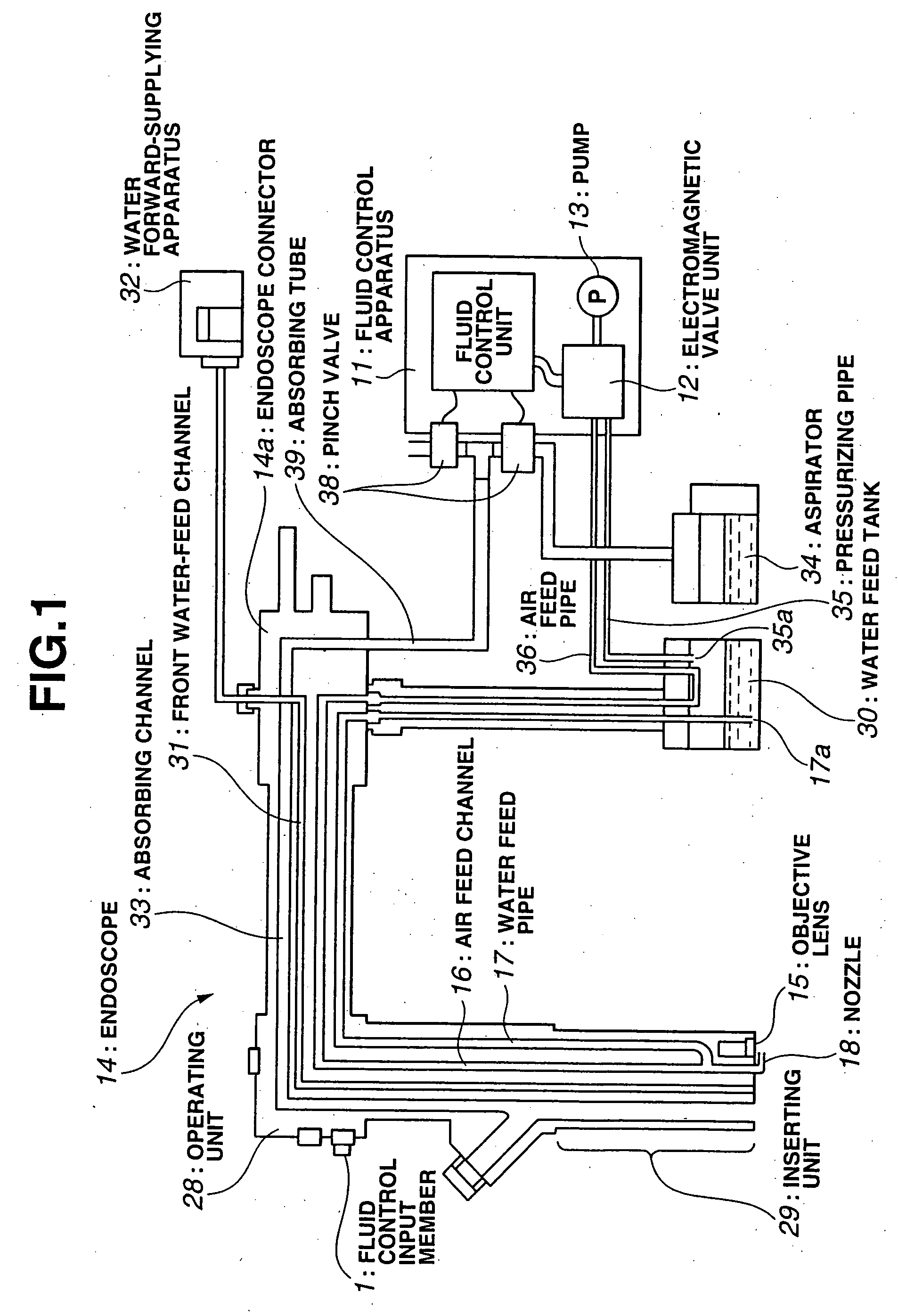
[0033]FIG. 1 is a schematic diagram showing the schematic structure of fluid channels and pipes in a fluid control apparatus connected to an endoscope used for a fluid control input device according to the present invention.

[0034] Referring to FIG. 1, an endoscope 14 comprises: an operating unit 28; and an inserting unit 29. In the endoscope 14, an air supplying channel 16, a water supplying channel 17, a water forward-supplying channel 31, and an absorbing channel 33 are formed. The operating unit 28 comprises various operating members, e.g., a fluid control input member 1, serving as a fluid control input device. The inserting unit 29 has, at the distal end thereof, image pickup means (not shown), and has, on the front surface of the distal end thereof, an objective lens 15 and openings of the channels.

[0035] The air supplying channel 16 and the water supplying channel 17 are formed to merge to one channel near the distal end of the inserting unit 29. Near the opening of the fron...

second embodiment

[0118] Next, a description is given of a fluid control input device according to the present invention.

[0119]FIG. 6 is a sectional view showing the detailed structure of a fluid control input device (fluid control input member 1B) according to the second embodiment of the present invention.

[0120] The structure according to the second embodiment basically uses the structure according to the first embodiment. However, the structures of the operating button, the button receiving member for receiving the operating button, and the click mechanism are different from those according to the first embodiment. Therefore, the same components as those according to the first embodiment are designated by the same reference numerals and a detailed description thereof is omitted. According to the second embodiment, the rubber cover for entirely covering the fluid control input device is arranged. The rubber cover is arranged similarly to that according to the first embodiment, and the drawing is n...

third embodiment

[0142] Next, a description is given of a fluid control input device according to the present invention.

[0143]FIG. 7 is a sectional view showing the structure of a fluid control input device (fluid control input member 1C) according to a third embodiment of the present invention.

[0144] According to the third embodiment, two two-step switches are used. Therefore, the structure of each of the switches (fluid control input device) basically uses the structure according to the first embodiment. However, the structure of a rubber cover 25C is slightly different from that according to the first embodiment. Therefore, the same components according to the first embodiment are designated by the same reference numerals and a detailed description thereof is omitted. An endoscope using the fluid control input device according to the third embodiment and a fluid control apparatus connected to the endoscope are the same as those according to the first embodiment and therefore, FIG. 1 is referred ...


PUM


Abstract

A fluid control input device for endoscope includes a moving member that is moved in accordance with the operation for instructing the switching of a channel arranged in the endoscope by an operator, a restoring member that restores the moving member to a predetermined restoring position, an operated amount detecting member that detects the amount of movement or operated force of the moving member by the operation of the operator and outputs information corresponding to the detected amount of movement or operated force, a covering member that is connected to an exterior member of the endoscope so as to watertightly cover the moving member while permitting the movement of the moving member, and an amount-of-force changing mechanism that changes the amount of operated force of the moving member after/before a predetermined position at which the moving member is moved by the operation of the operator to the predetermined position.

Description

CROSS REFERENCE TO RELATED APPLICATION [0001] This application is a continuation application of PCT / JP2004 / 006312 filed on Apr. 30, 2004 and claims benefit of Japanese Application No. 2003-133705 filed in Japan on May 12, 2003, the entire contents of which are incorporated herein by this reference.BACKGROUND OF THE INVENTION [0002] 1. Field of the Invention [0003] The present invention relates to a fluid control input device for endoscope, and more particularly, to a fluid control input device for endoscope applied to a fluid control apparatus for endoscope, which supplies the fluid by using a channel arranged in an endoscope and absorbs the intracavital tissue, serving as an operating member upon controlling the supply and absorption of the fluid. [0004] 2. Description of the Related Art [0005] Recently, an endoscope has been widely used in the medical field. In the endoscope used for the medical field, when an endoscope inserting unit is inserted in the body cavity, the intracavit...

Claims


Application Information

Patent Timeline
IPC IPC(8): A61B1/12A61B1/00A61B1/015H01H13/50
CPCA61B1/00068A61B1/015H01H13/50H01H2215/004
Inventor ARAI, KEIICHIMAEDA, TOSHINARIIKEDA, YUICHIMIYAGI, TAKAYASU
Owner OLYMPUS CORP
Why Eureka
Try Eureka