
Capsularhexis device

a technology of capsular hexis and apparatus, which is applied in the field of capsular hexis apparatus, can solve the problems of deteriorating vision, potentially blind complications, and radial tear

Inactive Publication Date: 2006-05-11
ALCON INC
View PDF42 Cites 108 Cited by
  • Summary
  • Abstract
  • Description
  • Claims
  • Application Information

AI Technical Summary

Benefits of technology

[0009] The present invention generally includes a flexible ring having a diameter suitable for an anterior chamber rhexis. Imbedded in the ring is a heating element or filament. Alternatively, the ring may contain a pair of adjacent, circular electrodes. The electrodes or heating filament are placed against the anterior capsule and electrical current is applied, causes localized heating around the electrodes or filament. The flexible nature of the ring and electrodes allow the ring to be folded so as to pass through a relatively small (<3 millimeter (mm)) incision, yet retain its full ring-shape once within the anterior chamber of the eye.

Problems solved by technology

When age or disease causes the lens to become less transparent, vision deteriorates because of the diminished light that can be transmitted to the retina.
Such a radial tear constitutes a complication since it destabilizes the lens for further cataract removal and safe intraocular lens placement within the lens capsule later in the operation.
Importantly, these complications are potentially blinding.
This is due to the extreme difficulty in controlling the path of the device.
Alternatively, the initial capsular incision is torn into a circular shape by grasping the leading edge with fine caliber forceps and advancing the cut in a very uncontrolled manner.
This is a very challenging maneuver and, even in the most experienced hands, the tearing motion can lead to an undesirable tear of the capsule toward the back of the lens.
Moreover, even if a tagless edge is ultimately produced, the size and / or position of the capsular opening may present a problem.
A small capsular opening can impair the safe removal of the lens nucleus and cortex and prevent proper intraocular lens insertion into the lens capsule.
The additional stresses necessary to accomplish the operation with a small or misplaced capsular opening put the eye at risk for zonular and capsular breakage.
Both of these types of breakage will likely increase the length and complexity of the operation and can result in vitreous loss.

Method used


Image

  • Capsularhexis device
  • Capsularhexis device
  • Capsularhexis device

Examples


Embodiment Construction

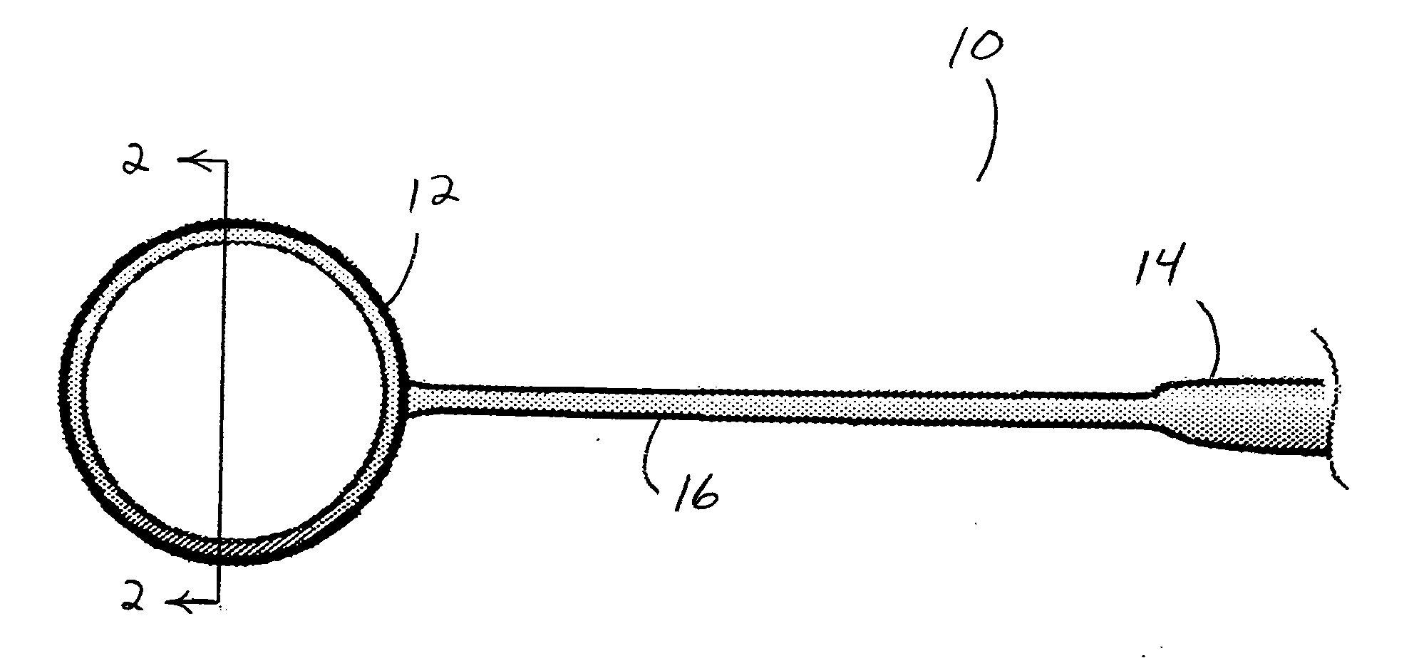
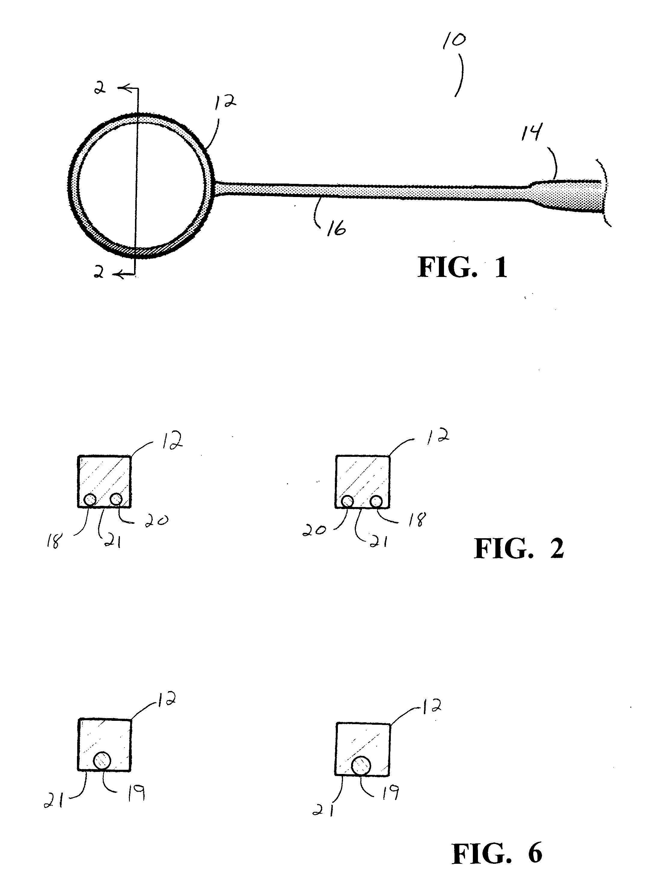
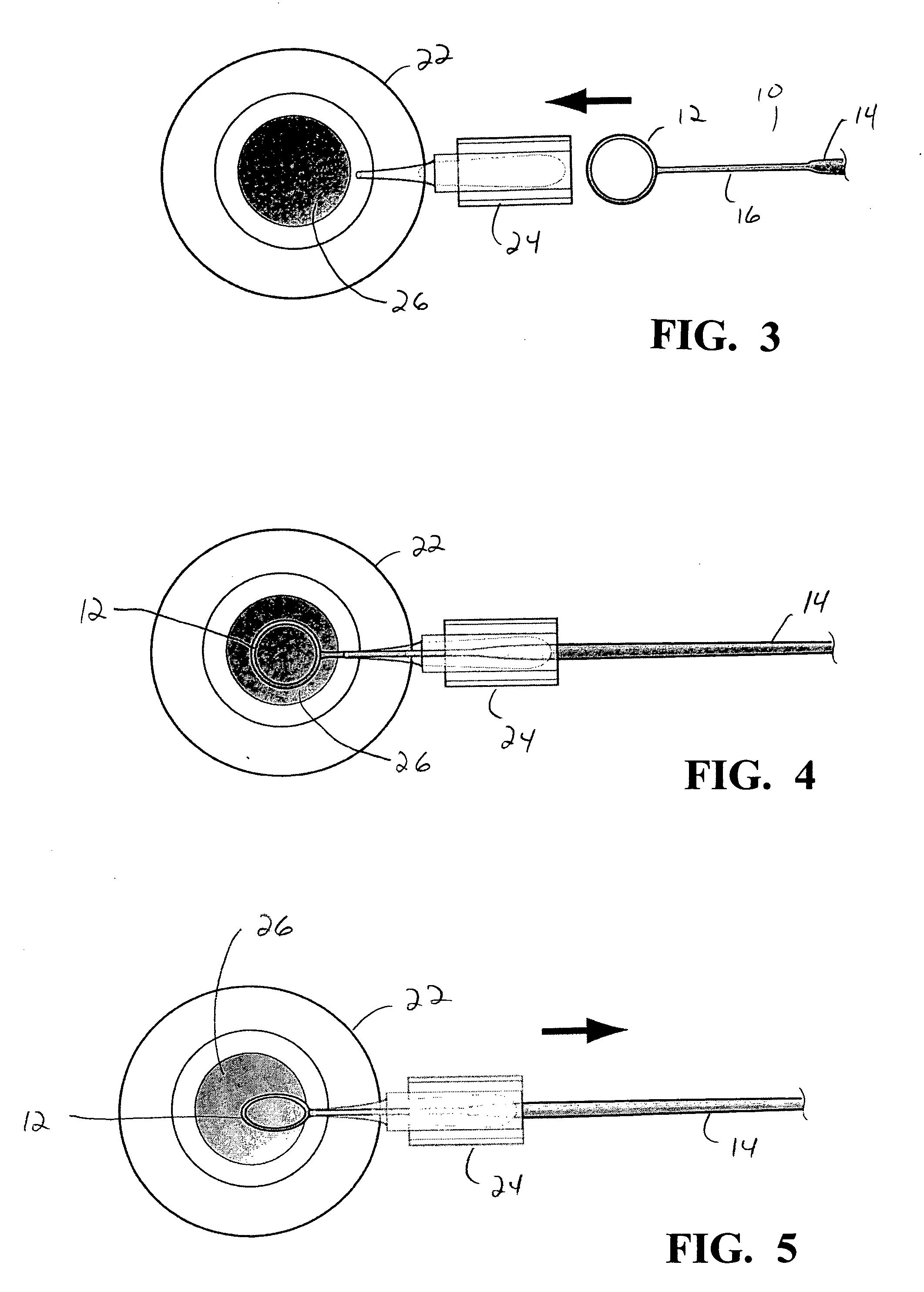
[0020] As seen in FIGS. 1 and 3-5, device 10 of the present invention generally include ring 12, handle 14 and shaft 16 connecting ring 12 with handle 14. Ring 12 may be made of any suitable flexible material such as an elastomer, acrylic or thermoplastic and may be any desired diameter, for example, between 3 mm and 6 mm. Embedded within ring 12 are two adjacent electrodes 18 and 20 made from a flexible wire or other conductive material. As seen in FIG. 2, concentric electrodes 18 and 20 are located at posterior surface 21 of ring 12, and may even project out a small distance from surface 21. Alternatively, ring 12 may contain single electrode or resistive wire 19, as shown in FIG. 6, embedded in ring 12 in a manner similar to electrodes 18 and 20. Electrodes 18 and 20, and resistive wire 19 are connected to a source of electrical current (not shown) through shaft 16 and handle 14. Shaft 16 and handle 14 may be made from an inexpensive material, such as a thermoplastic.

[0021] As b...


PUM


Abstract

A flexible ring having a diameter suitable for an anterior chamber rhexis. Imbedded in the ring is a heating element or filament. Alternatively, the ring may contain a pair of adjacent, circular electrodes. The electrodes or heating filament are placed against the anterior capsule and electrical current is applied, causes localized heating around the electrodes or filament. The flexible nature of the ring and electrodes allow the ring to be folded so as to pass through a relatively small (<3 mm) incision, yet retain its full ring-shape once within the anterior chamber of the eye.

Description

BACKGROUND OF THE INVENTION [0001] This invention relates generally to the field of cataract surgery and more particularly to an apparatus for performing a capsularhexis. [0002] The human eye in its simplest terms functions to provide vision by transmitting light through a clear outer portion called the cornea, and focusing the image by way of the lens onto the retina. The quality of the focused image depends on many factors including the size and shape of the eye, and the transparency of the cornea and lens. [0003] When age or disease causes the lens to become less transparent, vision deteriorates because of the diminished light that can be transmitted to the retina. This deficiency in the lens of the eye is medically known as a cataract. An accepted treatment for this condition is surgical removal of the lens and replacement of the lens function by an artificial intraocular lens (IOL). [0004] In the United States, the majority of cataractous lenses are removed by a surgical techni...

Claims


Application Information

Patent Timeline
IPC IPC(8): A61B18/18
CPCA61B18/082A61B18/14A61F9/00754
Inventor BOUKHNY, MIKHAIL
Owner ALCON INC
Learn More