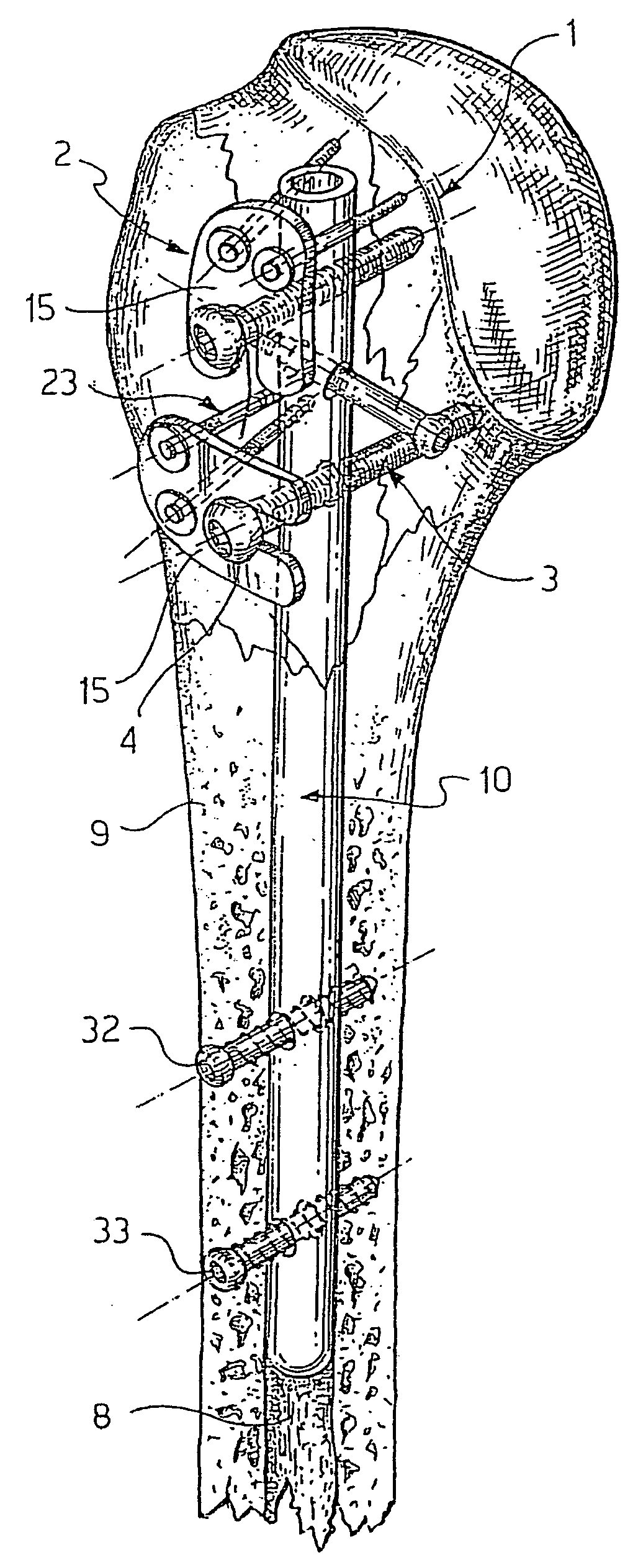
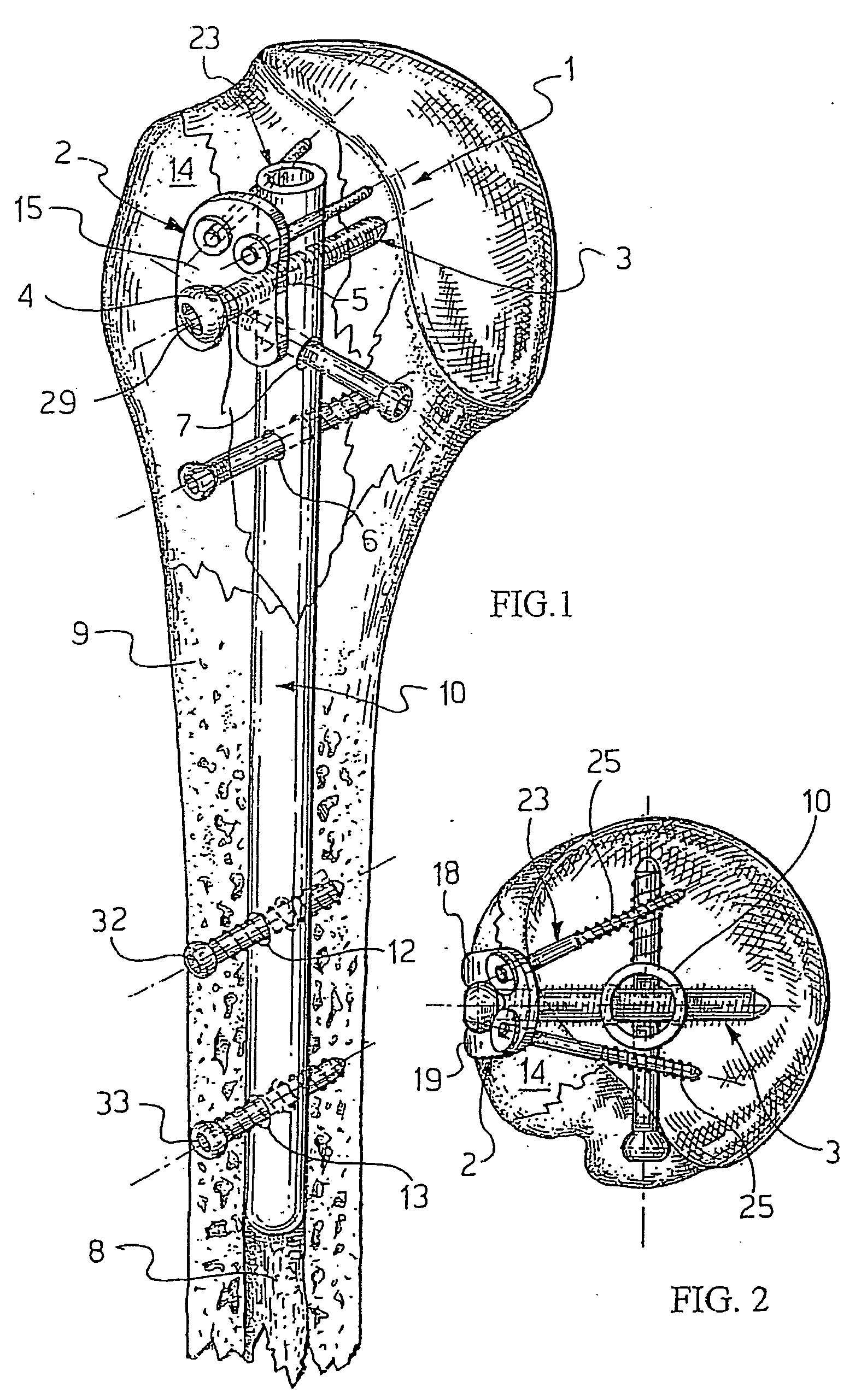
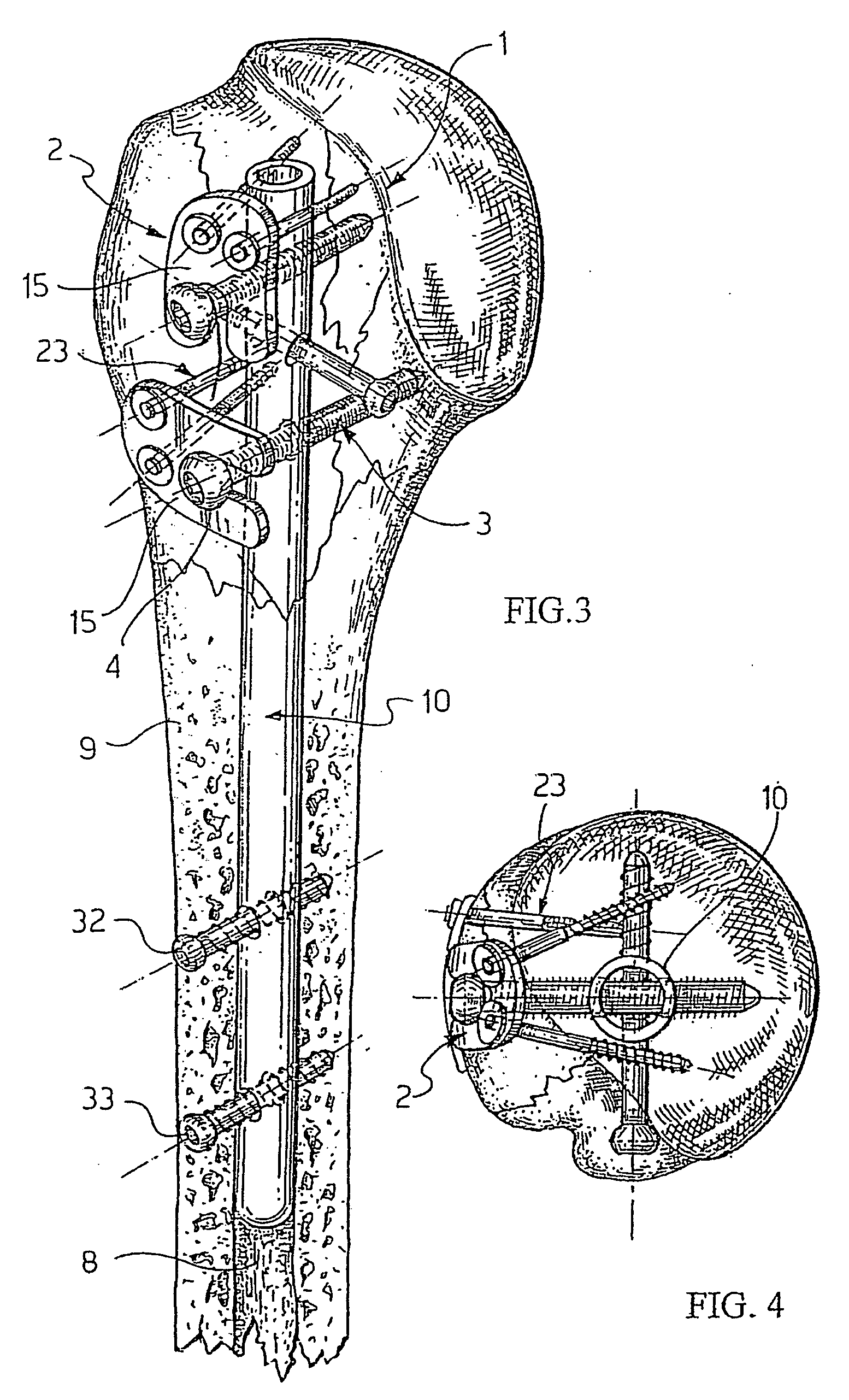
[0051] According to a first embodiment of the present invention the fixation system 1 includes the humeral nail 10, proximal locking screws 3 and at least one fastening device 2.
[0052] The humeral nail 10 includes a group of proximal transversal holes for corresponding locking screws 3. In this embodiment at least three transversal holes 5, 6, 7 are provided in the proximal portion of the humeral nail 10.
[0053] More specifically, since the humeral nail 10 is cannulated, each of the transversal holes 5, 6, 7 comprises a couple of holes that are realised in opposite walls of the nail and that may be axially aligned. For disclosure purposes we will consider these opposite holes as a single transversal hole.
[0054] Each of the transverse holes may be oriented at a selected angle with respect to the nail longitudinal axis; however, at least two holes 5, 6 of said group of proximal holes lie on a same plane while a third screw lies in a sagittal plane.
[0055] Advantageously, the locking screws 3 are fully-threaded and present a working head 4 and an opposite rounded end 34. The working head 4 has a recessed shaped seat 29 to receive a working key, not shown and used by the surgeon.
[0056] The form of the screw's thread will be detailed disclosed hereinafter; however, it must be noted that any specific shape and thread of the screws 3 may be used in the fixation system 1 according to the invention.
[0057] As above mentioned, at least one of the locking screws 3 has a corresponding screw head 4 that, according to the prior art, would normally abut against the nail 10 or against the cortex 14 of the humeral bone.
[0058] On the contrary, according to the system of the present invention the fastening device 2 is interposed between the screw head 4 and the bone cortex surface 14. More specifically, said fastening device 2 comprises at least an intermediate plate element 15 that is inserted between said screw head 4 and the bone cortex surface 14.
[0059] Thus, when the screw 3 is totally fastened, the screw head 4 abuts against the intermediate plate element 15 instead of against the bone cortex 14.
[0060] This solution allows the enlargement of the abutting surface of the locking screw head 4 against the bone cortex surface 14, thus allowing a stronger fastening action and avoiding a further rotation of the screw 3. Moreover, this solution allows the surgeon to fix together multiple fragments with a smaller cut.
[0061] Advantageously, said intermediate plate element 15 includes a slightly curved surface 16 to adhere perfectly to the bone cortex 14 surface, as shown in FIGS. 5 and 7. In a preferred embodiment the plate element 15 is slightly bent in both main axial directions thus presenting two opposite and parallel curved surfaces 16 and 17.
[0062] Just to give some indications about the shape and dimension of the intermediate plate 15, it worth to note that the whole plate element 15 could fit inside a circle having a diameter of eighteen mm and the plate thickness is of about 1 mm.
[0063] The intermediate plate 15 and the screw 3 are made by surgical steel, for instance . . . ??? As an alternative, they may be realised in Titanium or in a Titanium alloy.
[0064] As a possible alternative the plate 15 may be realised by a plastic material, for instance . . . ???
[0065] Moreover, the intermediate plate element 15 has a substantially rounded profile and comprises a couple of elongated arm portions 18, 19 that are inserted in an astride position on the screw rod just before a final fastening action on the screw head 4.
[0066] Each of said arm portions 18, 19 presents a rounded end 18a, 19a.
[0067] Said intermediate plate element 15 comprises an enlarged portion 21 having at least a seat 22, as shown in FIG. 9, for embracing at least a fragment fixation pin 23 to be inserted into the bone, as shown in FIGS. 1 and 2.
[0068] In a preferred embodiment said seat 22 is a hole 24 formed in said enlarged portion 21 of the intermediate plate 15. This hole 24 may have for instance a diameter of 2.5 mm.
[0069] In a preferred embodiment, at least two holes 24 are provided in said enlarged portion 21 and in alignment with each corresponding arm portion 18, 19, as shown in FIG. 6.
[0070] In a further embodiment of the present invention one of the holes 24 may be provided close to the end of one of the arm portions 18 or 19, as shown in FIG. 8.
[0071] According to the previous description the intermediate plate element 15 may be considered an open washer integrally formed with a flange portion 21.
[0072] The fragment fixation pin 23 is a thin rod 26, made of surgical steel, having a final threaded portion 25. The rod may have a diameter of 3 mm while the threaded portion of the rod may have an outside diameter less than 2.5 mm.
[0073] [Note: the drawings show little round washers around the fixation pin but they don't need to be used since the diameter of rod is larger than the diameter of the hole 24, so the rod may be cut just above the threaded portion and kept in place without a washer]
[0074] This fragment fixation pin is disclosed in the European Patent No. 0 642 323 in the name of the same applicant and shown schematically in FIG. 14.
[0075] After the surgeon has produced an anterior opening in the deltoid muscle to reach the fractured epiphyseal mass, a short incision is made in line with the deltoid fibers. Then, the deltoid fibers are divided to access to the fractured area and to the corresponding ematoma.
[0076] The nail 10 is inserted into the axis of the humeral shaft 9 and kept in place by the distal screws 32, 33. Then the fractures of the humeral head may be reduced by fixing the fragments against the humeral nail 10.
[0077] Using specific tools, the bone fragments (lesser tuberosity, greater tuberosity, humeral head, etc . . . ) once positioned, are precision drilled before receiving the screws 3.
[0078] The screws are locked and just before the final fastening of the screw the intermediate plate 15 between the screw head 4 and the bone cortex 14 in an astride position on the screw body. It worth to note that a very small incision of the deltoid muscle, for instance 4 cm, is required to insert the plate 15 and this aids healing.
[0079] When the intermediate plate element 15 is put into its final position and the screw 3 is fastened so that the screw head 4 abuts against the plate 15 then the fragment fixation pin 23 may be inserted in the bone through the hole 24.
[0080] The fragment fixation pin 23 may be inserted in the bone drilling a hole through the bone small enough to firmly engage the pin threads.
[0081] Advantageously, the fixation pins 23 may be oriented according to the needs of engagement of other possible fragments of the humeral head since the diameter of its threaded portion is a little smaller than the diameter of the hole 24.
[0082] The presence of the pin 23 has the double function to avoid displacement or rotation of the intermediate plate 15 and, in case of need, to fix a fragment of the humeral head.
[0083] According to a preferred embodiment of the invention a couple of fragment fixation pins 23 are inserted in the bone through the corresponding holes 24 of a plate 15 shaped as in the example of FIG. 5 or 8.
[0084] However, as previously mentioned, even one fixation pin 23 may be enough for the purpose of avoiding a displacement of the plate 15 and a plate 15 including a single hole 24 may be used.
[0085] In a further embodiment of the present invention, disclosed with reference to FIGS. 3 and 4, a couple of intermediate plate elements 15 may be used for fixation purposes.
[0086] Those plates 15 may even have different dimension and a second plate 15′ used in cooperation with the more distal of the proximal screws 3 may be greater than the other upper plate 15.
[0087] As a further alternative, the arm portions 18 and 19 of the second and more distal intermediate plate 15′ may be longer than those shown in FIG. 1 as a first embodiment of the present invention.
[0088] The final orientation of the plates 15 and 15′ may be different, the surgeon just needs to pay attention to the position of the holes 24 so that the fragment fixation pins 23 don't interfere with the nail 10 hidden inside the bone shaft 9, as shown in FIGS. 3 and 4.
[0089] Even the position of the plates 15 and 15′ may in some occasion be inverted, so that the larger plate 15′ may be fixed by the corresponding screw 3 in the more proximal position.
[0090] Referring now to FIGS. from 10, 11, 12 and 13 a further embodiment of the present invention is disclosed.
[0091] In this embodiment a humeral nail 30 is provided with at least a proximal transversal hole 27 including an internal partially threaded portion 28, clearly shown in FIGS. 11 and 12. This portion 28 may be considered a portion of nut screw, but even a knurl portion could meet the purposes of the invention.
[0092] As previously noted, the humeral nail is cannulated and each transversal hole comprises a couple of holes that are realised in opposite walls of the nail and that are axially aligned.
[0093] In this embodiment it's also important to identify the two opposite holes 27′, 27″ that form the transversal hole 27.
[0094] Each screw 3 has an outside thread diameter smaller than the diameter of the transversal hole 27 that receives the screw and the internal threaded portion 28 doesn't interfere with the screw during the normal insertion.
[0095] In a preferred embodiment the internal threaded portion 28 is provided in the hole 27′ closer to the screw head 4.
[0096] The screw 3 may be put in place and fixed according to the previous disclosure, thus with the aid of the intermediate plate 15.
[0097] In case of a undesired movement or displacement of the screw 3 after its final fastening, the internal threaded portion 28 solve the problem engaging the threaded portion of the screw 3 at least in a crest to crest fashion, as shown in FIG. 12.
[0098] As previously mentioned, the screw 3 may have any specific shape and thread; however, a preferred screw structure is disclosed hereinafter.
[0099] The screw 3 comprises a screw body 31 that is fully threaded.
[0100] This threaded body has a substantially cylindrical shape with a constant diameter ending in the rounded end 34.
[0101]FIG. 15 is an enlarged view of the profile of the threaded portion 5 according to the invention.
[0102] Advantageously, the threaded portion has at least a section formed with a constant pitch p, preferably a 0.45 mm pitch, and comprises threads 35 having a triangular profile in cross-section with a cusp or acute apex angle of 60°.
[0103] The facing walls of two adjacent threads form an angle α of no more than 60°.
[0104] Advantageously, the bottom portion of the threads between adjacent inner walls of the threads 35 is slightly concave and rounded, effective to ease the material flow and relieve bone stress during the screw penetration.
[0105] The radius of the bottom rounded portion is 0.5 mm.
[0106] The thread height h is 0.27 mm and it is constant along the thread profile.
[0107] This thread would allow also a conical profile to be used.
[0108] The screw 3 of this invention distributes the stress better than conventional screws. Moreover, the screw 3 of this invention shows to have a better distributed compression even in the absence of interference, that is in situations of an oversize pre-drilled hole, lysis or osteoporosis.
[0109] As a whole the system according to the present invention facilitates a fast anatomical reduction of the fracture and ensured a fast consolidation as well.
[0110] Moreover, this system requires a very small incision to be made in the muscle surrounding the bone and this aids healing.
[0111] Moreover, the use of the plate 15 allows one to fix together multiple fragments with a smaller cut.