Connectivity between a scan tool and a remote device and method

a remote device and scan tool technology, applied in the field of automotive diagnostics, can solve the problems of affecting the operation of the diagnostic tool, the failure of the diagnostic routine, and the limited reporting of data of the present external diagnostic and display apparatus, and achieve the effect of easy program upgrades/modifications

Inactive Publication Date: 2006-05-11
SPX CORP
View PDF26 Cites 103 Cited by
  • Summary
  • Abstract
  • Description
  • Claims
  • Application Information

AI Technical Summary

Benefits of technology

[0010] The foregoing need for a diagnostic tool wherein the diagnostic software can be easily upgraded is satisfied to a great extent by the present invention which is directed to a portable diagnostic tool that provides easy program upgrades / modifications via remote updating when, for example, diagnostic application programs are upgraded or new algorithms are developed or adapted. The diagnostic tool functions with an internal operating system that accesses software programs in the form of diagnostic routines residing in the internal memory, or on an external memory card. Each diagnostic routine is compiled and linked separately from the operating system and is separately downloadable into a non-volatile storage. device, such as the non-volatile memory, of the diagnostic tool.

Problems solved by technology

Present external diagnostic and display apparatus, known to those skilled in the art as scan tools, are commonly limited to reporting the data acquired by the onboard control computer itself.
However, in conventional practice, these diagnostic routines have been problematic in the area of upgrades.
These program upgrades and additions have therefore been difficult to accomplish and have resulted in downtime for the equipment that are inconvenient for the user.
A direct wired approach, from the scan tool to another user interface of a remote device, such as a PC, may impose some difficulties to technicians performing diagnostic operations.
For example, the wires can be cumbersome to maneuver around as technicians perform / analyze testing operations on the vehicle.
Additionally, the operating range of the Scan Tool is necessarily limited to the length of any connected wire(s).

Method used


Image

  • Connectivity between a scan tool and a remote device and method
  • Connectivity between a scan tool and a remote device and method
  • Connectivity between a scan tool and a remote device and method

Examples


Embodiment Construction

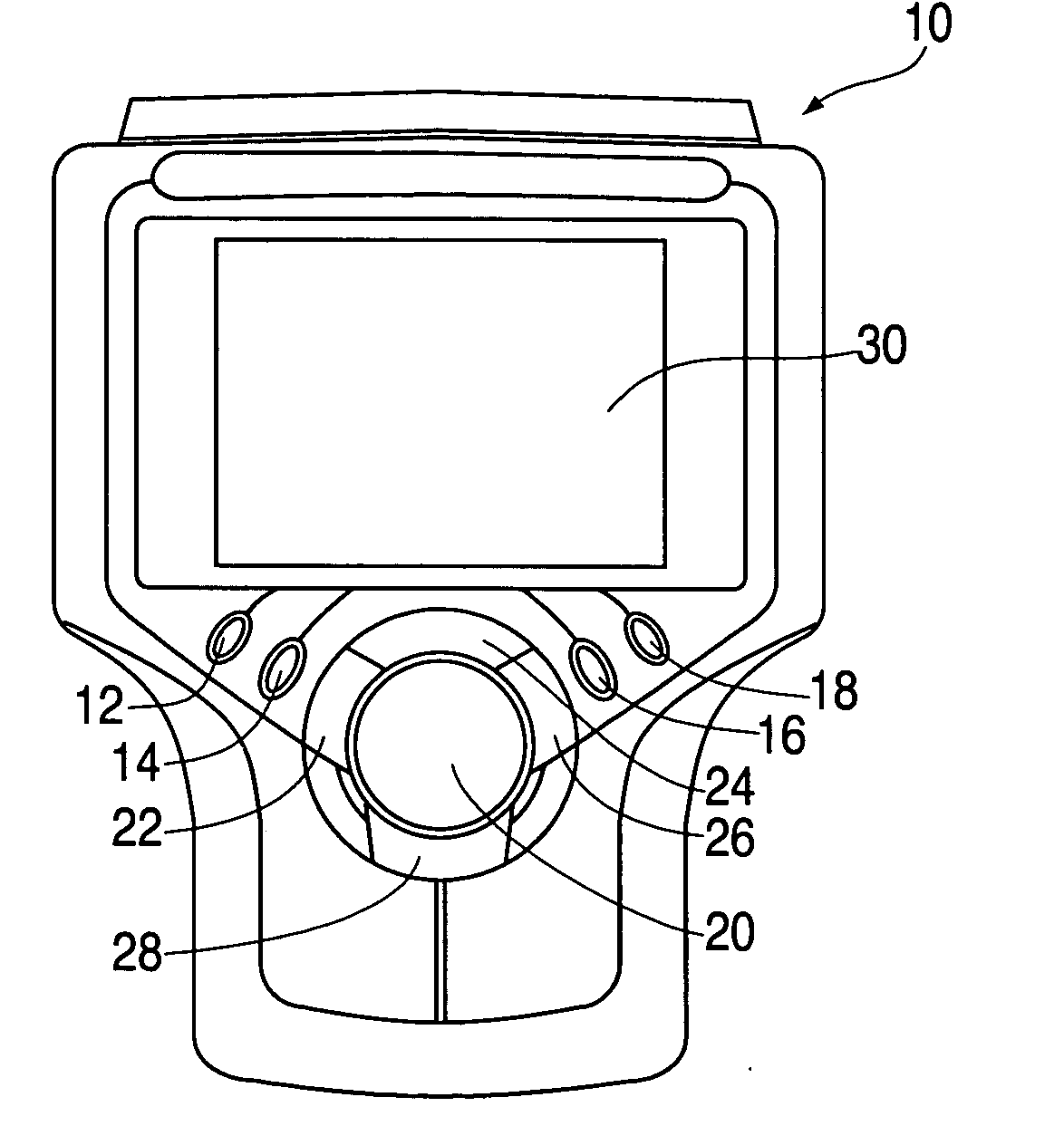
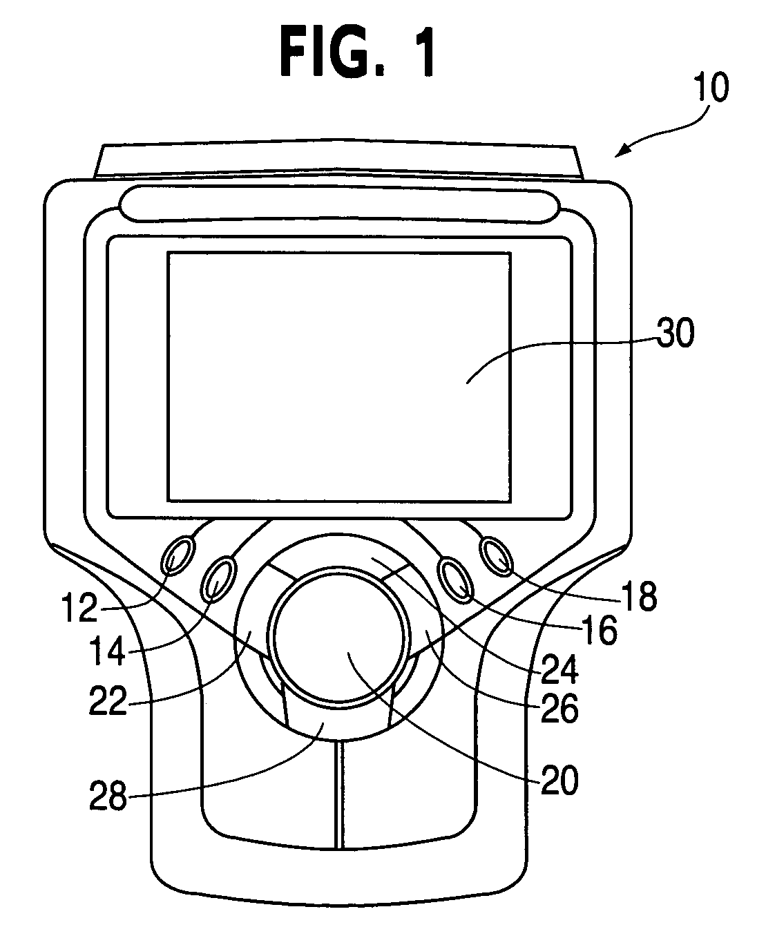
[0033] Referring now to the figures wherein like reference numerals indicate like elements, in FIG. 1 there is shown a diagram of a diagnostic tool 10 according to an embodiment of the present invention. The command key operations of the diagnostic tool, shown on the tool's front panel, consist of four areas: function keys 12, 14, 16, and 18, a cursor or direction key 20, and action keys 22, 24, 26, and 28. These keys are used for enter in instructions and / or data in the tool.

[0034] The function keys 12, 14, 16, and 18 activate unique commands. Each command function is displayed on the screen 30 of the diagnostic tool 10. The function 5 keys 12, 14, 16, and 18 are controlled by the software program and will preferably change as different parts of a diagnostic routine or procedure are displayed. The directional key 20 moves a command bar in a left, up, right or down direction on the screen 30.

[0035] The action keys 22, 24, 26, and 28 activate an action or request an application. In...


PUM


Abstract

A hand-held diagnostic tool is designed to operate and easily upgrade software applications developed for automotive diagnostics. The diagnostic tool, which communicates with a plurality of motor vehicle control units, provides application upgrades and/or modifications and/or new algorithms that are developed/adapted via remote updating. The tool comprises full diagnostic capability capable of receiving diagnostic data from a motor vehicle for storage, analysis and/or further data transfer to a remote device. The tool may further comprise wireless capability to perform data transfer operations. Remote updating is accomplished through a number of external ports on the tool that facilitate modem, Ethernet and wireless communications, including point-to-point protocol connection to the Internet.

Description

FIELD OF INVENTION [0001] The present invention generally relates to the field of automotive diagnostics. More particularly, the present invention relates to a portable device designed to interface with onboard motor vehicle control computers, receive and / or collect vehicle diagnostic information and transmit the vehicle diagnostic information to a remote device. BACKGROUND OF THE INVENTION [0002] Onboard control computers have become ubiquitous in motor vehicles, as safety, economy, and emissions requirements have continued to escalate, and conventional designs for reciprocating engines, friction braking systems, collision safety apparatus, and traction control devices have proven unequal to the requirements set out in law and the implicit demands of competitors' achievements. Successive generations of onboard control computers have acquired increasing data sensing and retention capability as the electronic art has advanced. [0003] Present external diagnostic and display apparatus,...

Claims


Application Information

Patent Timeline
Patent Type & Authority Applications(United States)
IPC IPC(8): G06F11/00
CPCG07C5/008G07C2205/02
Inventor LIPSCOMB, EDWARDLIEBL, TROYSHAH, HEMANGKALIVARADAN, LAKSHMYCHINNADURAI, MANOKAR
Owner SPX CORP
Why Eureka
Try Eureka