Rotatable rod grip

Inactive Publication Date: 2006-05-18
AYOUB IHAB AHAB
View PDF23 Cites 9 Cited by
  • Summary
  • Abstract
  • Description
  • Claims
  • Application Information

AI Technical Summary

Benefits of technology

[0022] As used herein, the term “gimbal” has a preferred meaning of “a device for stabilizing an object in three-dimensional space.” A gimbal need not be in a fixed position, and in fact may pivot in various directions. A gimbal may also include a “gimbal pin” that may operatively co

Problems solved by technology

In some instances, pumping of the rod may continue for long periods of time and operator fatigue may affect the likelihood of landing of a hooked fish.
Rotation of the rod during use is often undesirable for a number of reasons.
In such a situation, the operator will experience resistance in the operation of the rod due to the resistance to rotation from the gimbal and/or gimbal pin, or the rod may detach from the gimbal and/or gimbal pin, thereby becoming unstable.
This may result in increased fatigue and possible injury to the operator's wrist.
Displacement of the line within a roller guide may result

Method used


Image

  • Rotatable rod grip
  • Rotatable rod grip
  • Rotatable rod grip

Examples


Embodiment Construction

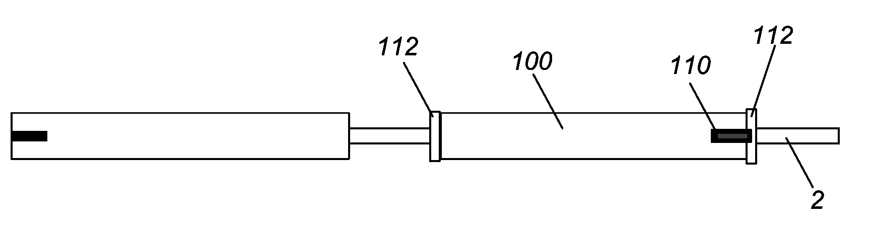
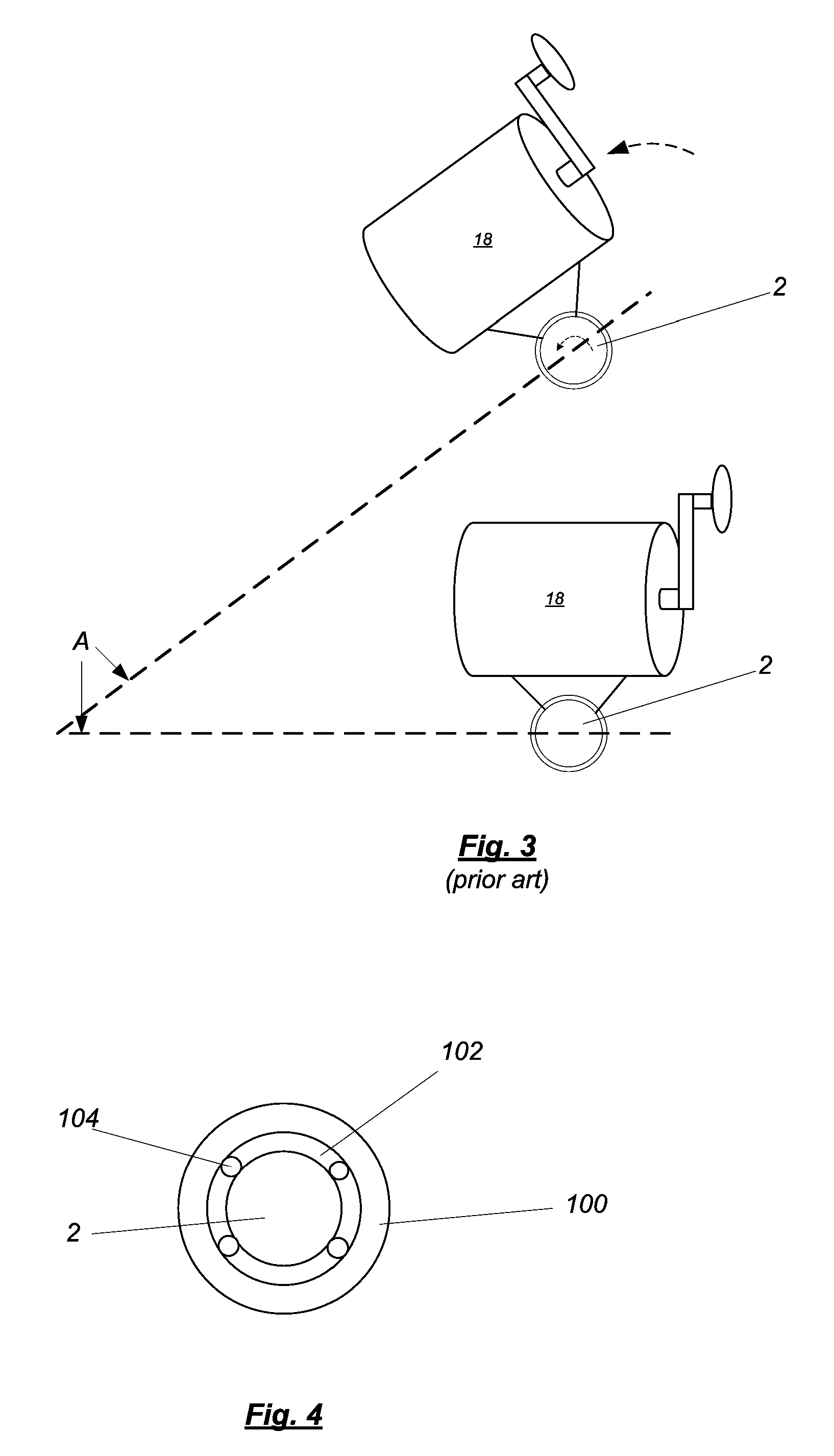
[0033] As shown in FIG. 4, one embodiment of the invention comprises a first member 100 disposed along the circumference of a section of a fishing rod shaft 2. A rotational interface 102 between the first member 100 and shaft 2 permits rotation of the first member 100 about the longitudinal axis of the shaft 2. One or more rotational elements 104 may be disposed within the rotational interface 102 to facilitate rotation. A rotational element 104 may be of any type known in the art including, but not limited to, lubricants, ball bearings, and roller bearings. Rotation of the first member 100 about the shaft 2 may also be achieved by any other means known in the art.

[0034] In one embodiment, rotation of the first member 100 may be limited to a predetermined range. Furthermore, it may be desirable to provide a predetermined ease of rotation such that the first member 100 will not rotate of its own accord. It may also be desirable to bias the first member 100 such that it will maintain...


PUM


Abstract

A rod grip that may rotate around a fishing rod shaft is disclosed The amount of rotation may vary, and the rod grip may be rotationally locked to the fishing rod, or some component thereof, when rotation of the rod grip is not desired. A fishing rod is also disclosed, having such a grip. A manufacturing method is disclosed for the manufacture of a rotatable rod grip and a fishing rod having such a grip. The grip may be retrofit onto existing fishing rods, whether or not they include an existing traditional grip. Lubricant, ball bearing, roller bearings and other approaches to relative movement may be used to facilitate the rotation of the disclosed grip.

Description

CROSS-REFERENCE TO RELATED APPLICATIONS [0001] This application claims priority to U.S. Provisional Application No. 60 / 522,902, filed Nov. 18, 2004, and hereby incorporated by reference in its entirety.BACKGROUND OF INVENTION [0002] The invention relates generally to a rotatable grip for a fishing rod. BACKGROUND ART [0003] Fishing rods are one of the most common devices used by recreational and commercial fishermen alike for capturing fish and other marine organisms. As shown in FIG. 1, a fishing rod (or “rod”) typically will include a number of components, including a rod shaft 2, a lower or butt section 4 (the “rod butt” or “butt”), a grip section 6, and one or more guides 8 disposed along the upper section of the rod. The grip section 6 is usually disposed near and / or in the butt section 4 and typically comprises a lower grip 10 (nearer the butt end 12) and an upper grip 14, with a reel seat 16 disposed therebetween. The butt end 12 may also include a notch 13 or similar configu...

Claims


Application Information

Patent Timeline
IPC IPC(8): A01K87/08A01K87/00
CPCA01K87/00A01K87/08
Inventor AYOUB IHAB (AHAB)
Owner AYOUB IHAB AHAB
Why Eureka
Try Eureka